3–2 D485 MODBUS TO DEVICENET CONVERTER – USER GUIDE
DATA EXCHANGE
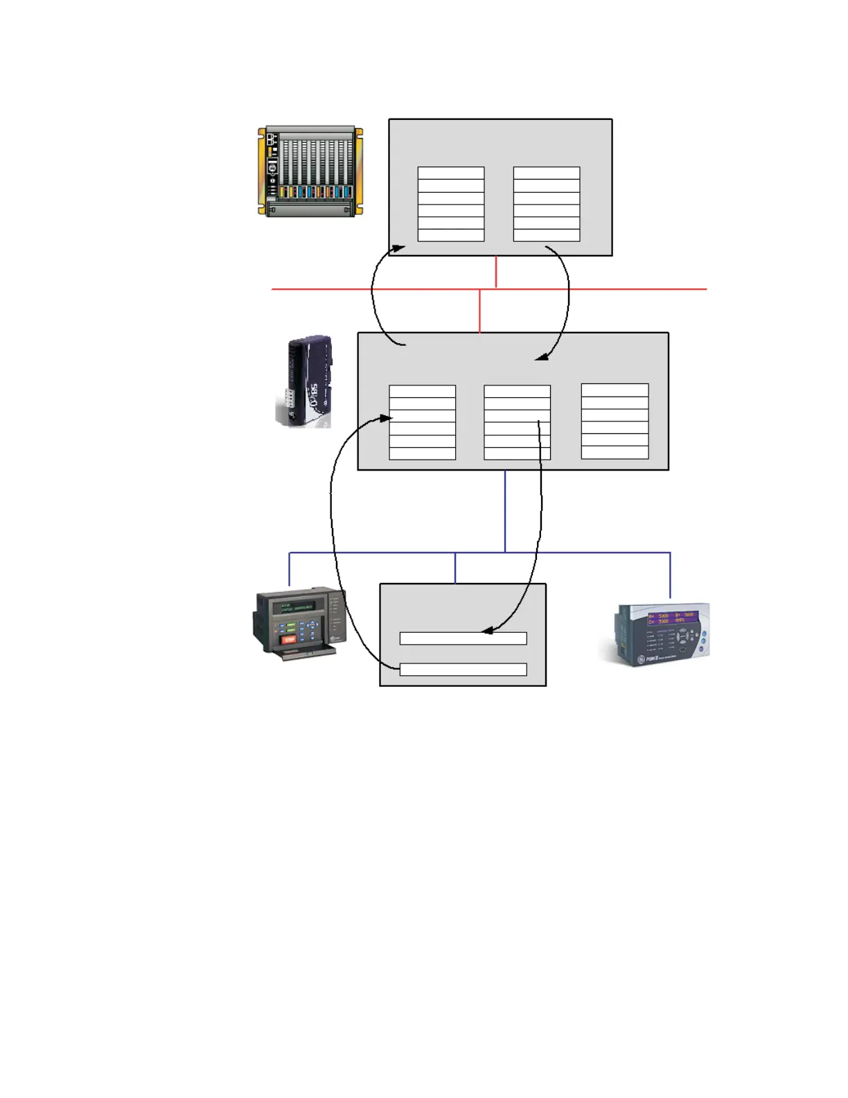
Figure 3-1: Data exchange overview
INTERNAL MEMORY
BUFFER STRUCTURE
The internal memory buffer can be seen as a memory space with three different types of
data; input data, output data and general data.
• Input data: This is data that should be sent to the fieldbus. The D485 can handle up to
512 bytes of input data.
• Output data: this is data recieved from the fieldbus. The D485 can handle up to 512
bytes of output data.
• General data: This data cannot be accessed from the fieldbus, and is used for
transfers between nodes on the sub-network, or as a general “scratch pad” for data.
The D485 can handle up to 1024 bytes of general data.
The PLC exchanges data
via the DeviceNet network
between its internal input
area and the input area
of the D485
DeviceNet network
The PLC exchanges data
via the network
between its internal output
area and the output area
of the D485
DeviceNet
The data in the input area of
the D485 contains data received
from nodes on the Modbus
sub-network (sent in to the D485
from the sub-network)
The data in the output area of the
D485 contains data received from
In this case, it is the CT PRIMARY
setting of the PQMII meter
(sent out from the D485 to the sub-network).
DeviceNet
0x0000 0x0200 0x0400
Input data area Output data area General data area
Modbus sub-network
Current Ia CT PRIMARY
Internal memory buffer
of the D485
PLC memory
I/O inputs
I/O outputs
Current Ia
CT PRIMARY
Modbus slave (e.g. PQMII)
CT PRIMARY setting
Current Ia actual value