APPLICATION EXAMPLE
D485 MODBUS TO DEVICENET CONVERTER – USER GUIDE 9–15
GROUPING I/O DATA By default, all mapped I/O input data is grouped in one attribute and is used for polled
production data, and all mapped I/O output data is used as polled consumption (output)
data. The mailbox commands can be used to split this data into different attributes.
We have mapped 24 bytes of input data and 4 bytes of output data. The following
procedure splits the input data in 16 bytes of I/O input data and 8 bytes of explicit input
data.
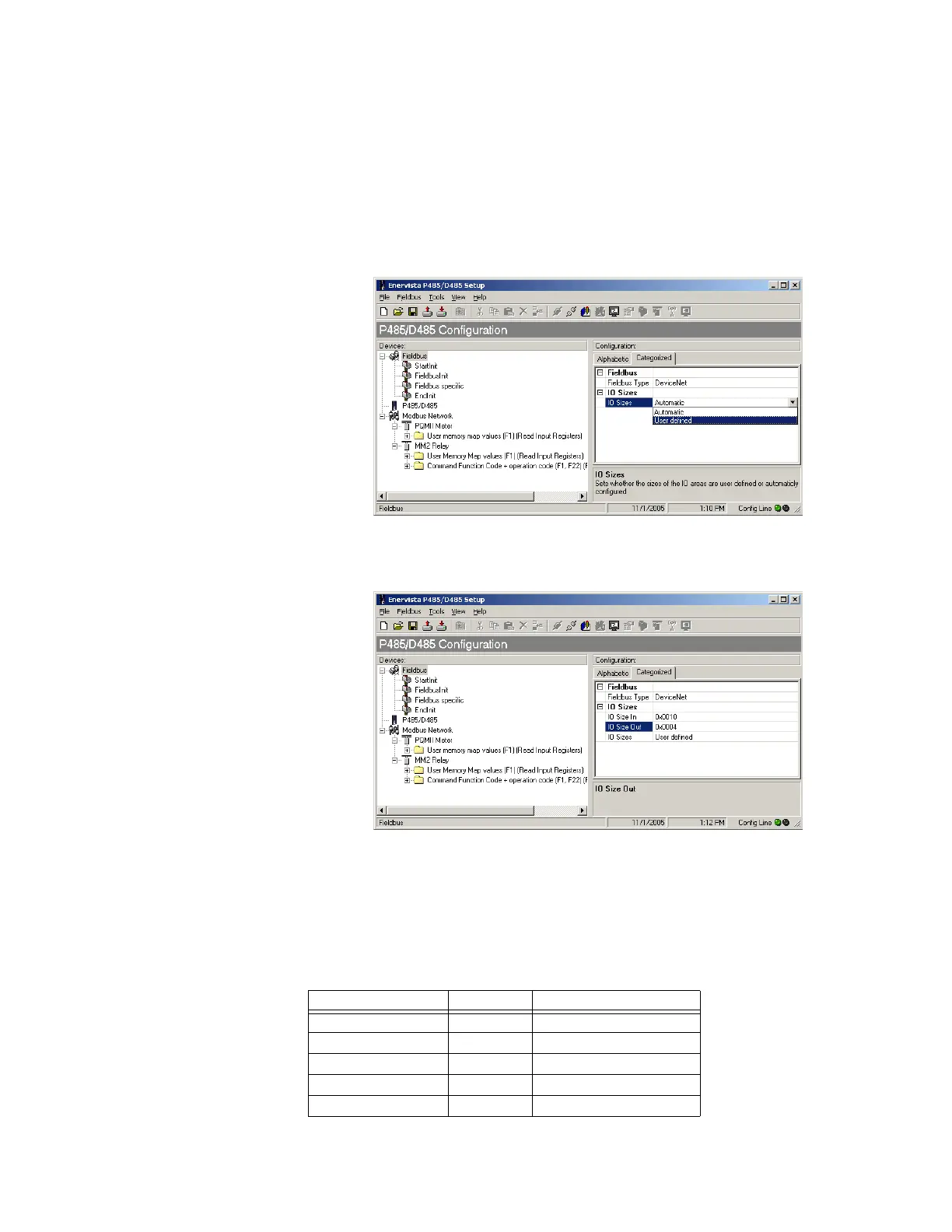
1. Click on the Fieldbus item and change IO sizes option to “User defined” as shown
below.
Figure 9-25: User defined IO sizes
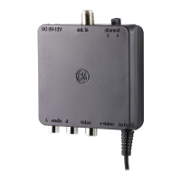
2. Set the IO Size In (IO input data size) to 16 bytes (i.e. 0x000A) and the IO Size Out (IO
output data size) to 4 bytes.
Figure 9-26: Setting the IO sizes
3. With this setting, input data is divided into two parts: the first 16 bytes of input is IO
input data and remaining 8 bytes is explicit input data. All 4 bytes of output data is IO
output data.
I/O DATA INPUT MAPPING The IO data can be further assigned to different attributes of I/O data input mapping object
A0h. Define the following five attributes out of 16 bytes of data.
Attribute Bytes Assignment
Attribute 1 (Input 1) 6 bytes Phase current Ia, Ib, Ic
Attribute 2 (Input 2) 2 bytes Average phase current
Attribute 3 (Input 3) 2 bytes Neutral current
Attribute 4 (Input 4) 4 bytes Average phase voltage
Attribute 5 (Input 5) 2 bytes Motor status