EasyManuals Logo

GE F650 User Guide

GE F650
323 pages
To Next Page IconTo Next Page
To Previous Page IconTo Previous Page
Page #10 background imageLoading...
Page #10 background image
1-4 F650 Digital Bay Controller GEK-113000AE
1.1 IMPORTANT PROCEDURES 1 GETTING STARTED
1
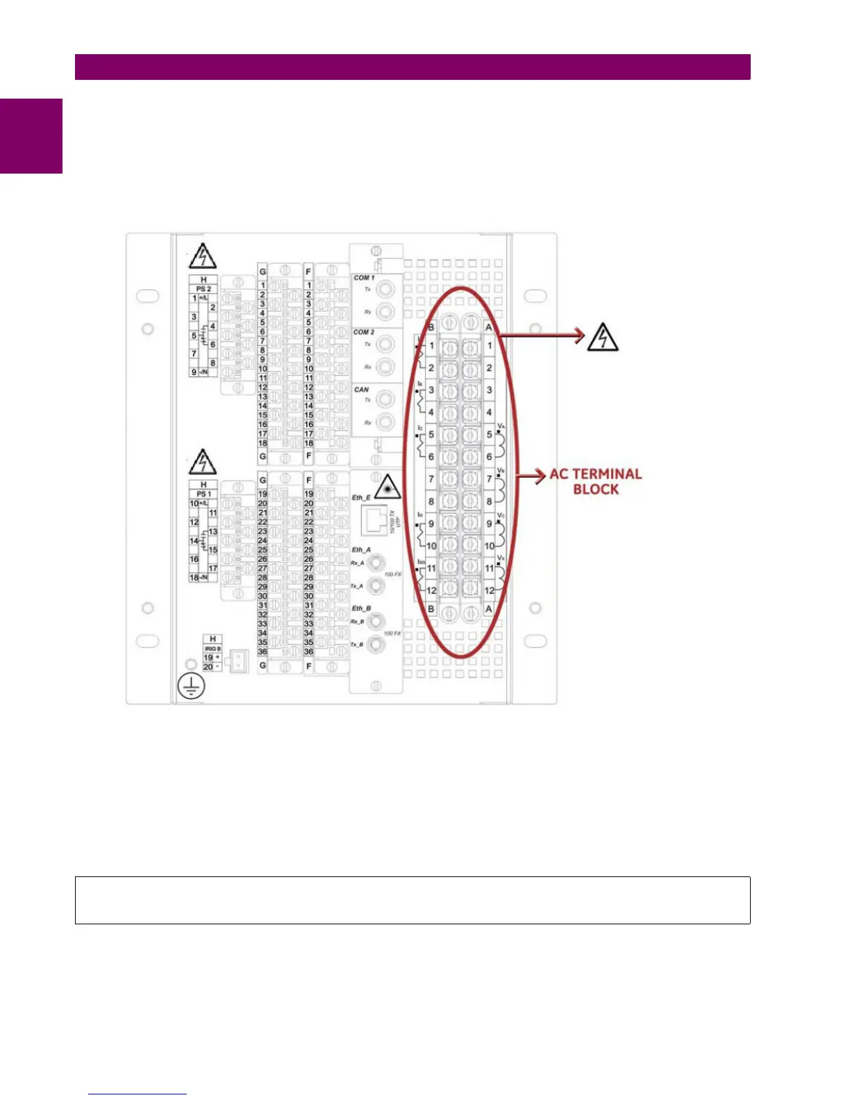
1.1.1.2 MAGNETIC MODULE TERMINALS
The transformer module for the VTs and CTs is already connected to a female connector screwed to the case. The current
inputs incorporate shorting bars, so that the module can be extracted without the need to short-circuit the currents
externally. It is very important, for safety reasons not to change or switch the terminals for CTs and VTs.
Figure 1–3: REAR VIEW OF F650 UNIT
GE Multilin will not be responsible for any damage of the relay, connected equipment or personnel
whenever these safety rules are not followed.

Table of Contents

Other manuals for GE F650

Questions and Answers:

Question and Answer IconNeed help?

Do you have a question about the GE F650 and is the answer not in the manual?

GE F650 Specifications

General IconGeneral
ModelF650
CategoryController
Frequency50/60 Hz
DisplayLCD
TypeFeeder Protection Relay
ApplicationFeeder Protection and Control
Communication ProtocolsDNP3, Modbus, IEC 61850
Protection FunctionsOvercurrent, Earth Fault
ManufacturerGeneral Electric
Input Voltage24-250 VDC/VAC

Related product manuals