GEK-113000AE F650 Digital Bay Controller 1-3
1 GETTING STARTED 1.1 IMPORTANT PROCEDURES
1
1.1.1.1 COMMUNICATION BOARDS WITHDRAWAL / INSERTION
The modular design of the relayallows for the withdrawal and insertion of the communication module.
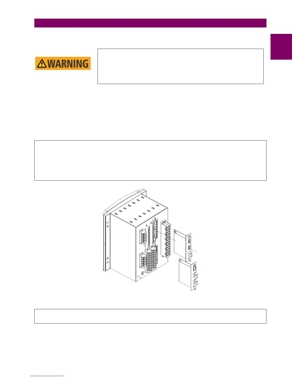
Figure 1–2: shows the location of communication modules on the rear part of the relay. Qualified personnel must carry out
the insertion or extraction of the communication boards only after interrupting the relay auxiliary voltage and ensuring that
all the rear terminals are potential free.
Communication boards are installed on the rear of the unit, the upper port being reserved for the asynchronous
communications board and CAN, and the lower port for the ETHERNET board in any of its configurations.
Figure 1–2: MODULE WITHDRAWAL/INSERTION
MODULE WITHDRAWAL AND INSERTION SHALL ONLY BE PERFORMED BY
DULY QUALIFIED SERVICE PERSONNEL. FOR PERSONAL SECURITY
PURPOSES, BEFORE ACCOMPLISHING ANY WITHDRAWAL OR INSERTION
OPERATION, THE RELAY MUST BE POWERED OFF AND ALL THE REAR
TERMINALS MUST BE POTENTIAL FREE. THE RELAY MUST BE GROUNDED
USING THE REAR GROUNDING SCREW.
Before performing any of these actions, control power must be removed from the relay and all the rear terminals must be
potential free. A grounded antistatic wristband must be used when manipulating the module in order to avoid
electrostatic discharges that may cause damage to the electronic components.
WITHDRAWAL: Loosen the small screws that keep the faceplate in place and extract the module.
INSERTION: Insert the module and press it firmly in the case, until it is completely fixed. After this, bolt the faceplate
screws and replace the control power. Check that the relay is fully operative.
GE Multilin will not be responsible for any damage of the relay, connected equipment or personnel whenever
these safety rules are not followed.