5-10 F650 Digital Bay Controller GEK-113000AE
5.1 UPGRADE FROM VERSION BELOW V7.00. 5 BOOTCODE AND FIRMWARE UPGRADE
5
It may be due there is no communication via Ethernet port. At this moment, serial communications works properly, the relay
flash memory has been erased and the upgrade procedure must be completed to start working with the unit. If the
procedure is not completed, the HMI will show the message "Os Loading..." and the relay will not start up.
Then please check statements of point 4 above
If all the above points are correct but the problem persists:
-Disable and Enable the Ethernet connection while the files are being sent (during the “Sending file...” message -
previous figure). To do this, in Windows OS go to STARTUP>CONTROL PANEL>NETWORK
CONNECTION>LOCAL NETWORK>Right mouse key>Disable. Now the Local Network status Icon will be shown as
Disabled. In the same screen with Right mouse key over LOCAL NETWORK click Enable and wait until Enabled
status is shown.
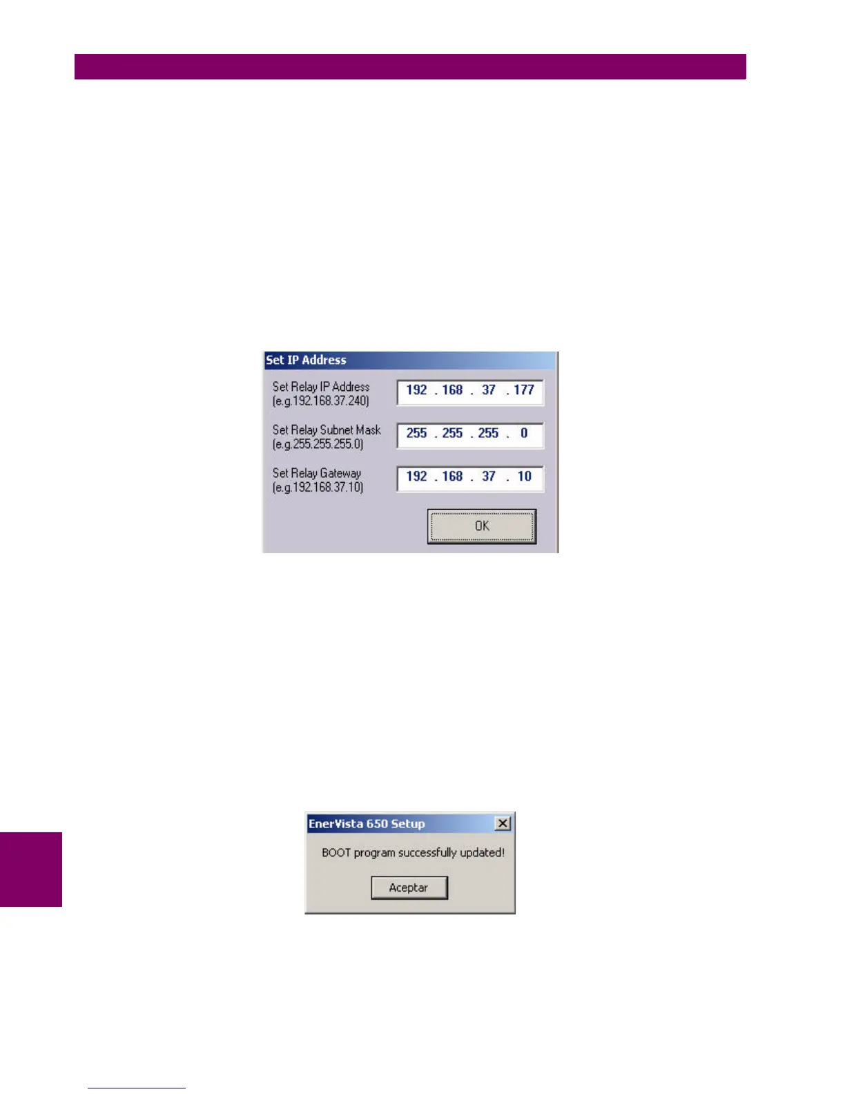
20. Once the memory has been erased and the files upgraded in the relay, the parameters for the Ethernet
communications must be set. The requested values are the IP address and the gateway.
Figure 5–19: IP ADDRESS SETPOINT WINDOW
These values should match the LAN structure where the relay will be connected.
The relay IP address should have the first three octets corresponding with the gateway and the last octet must be a
free IP address reserved to the relay to avoid possible collisions with other devices.
The gateway must be the one used in the LAN structure connecting the relay
21. After assigned the Ethernet parameters, the upgrade of the boot code will be completed successfully (figure below).
22. New momentarily window will display: "Setting Default IP address”, and then it follows with:
Figure 5–20: BOOTWARE UPGRADE SUCCESSFUL PROCESS
After boot code upgrade, the equipment firmware must also be upgraded (hereafter).

 Loading...


