GEK-113000AE F650 Digital Bay Controller 2-5
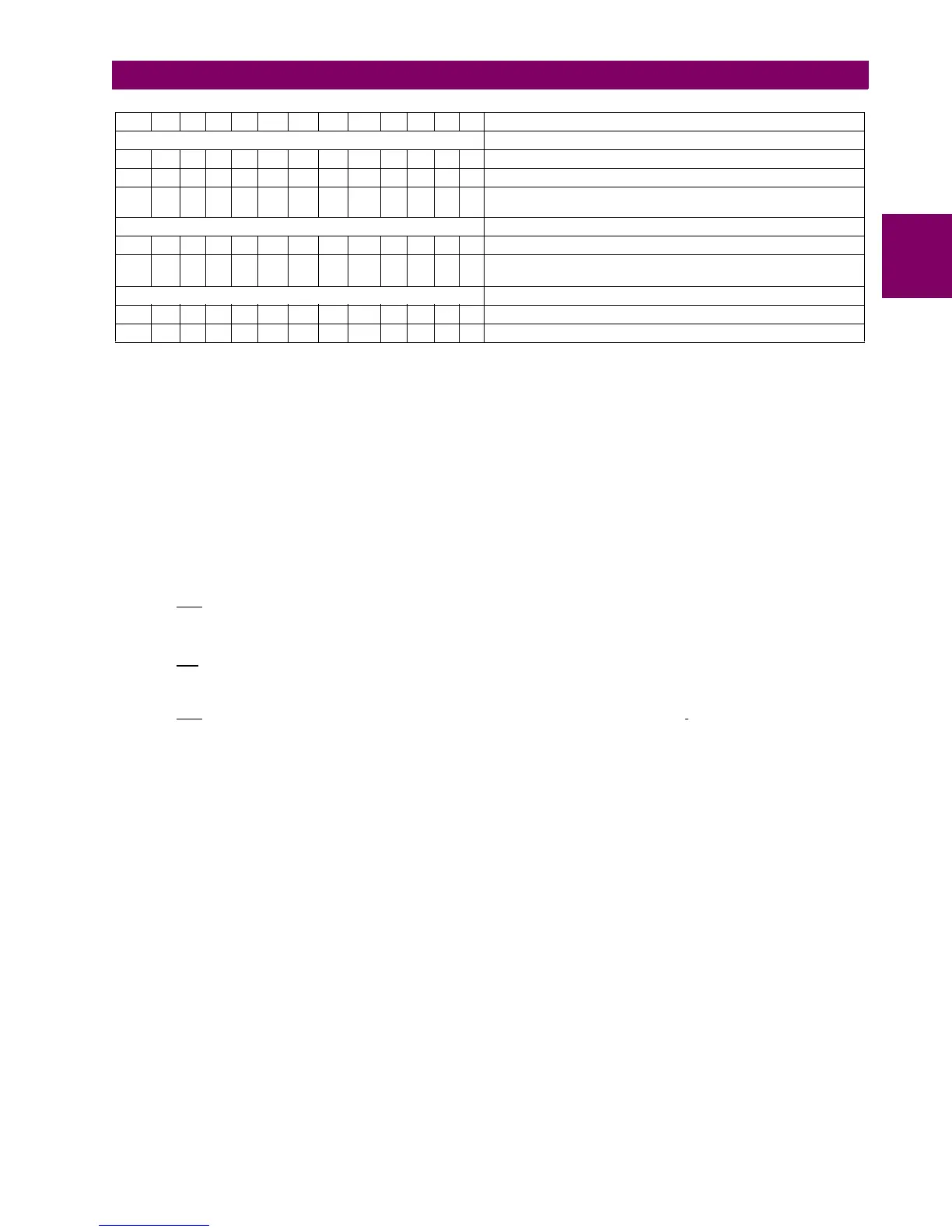
2 PRODUCT DESCRIPTION 2.4 ORDERING CODE
2
SPECIAL MODELS MOD001 (Abbreviation "+M1"): 6A output contacts instead of 16A.
Notes:
(*) For firmware version 7.00 or above, Port E is intended for maintenance purposes.
(1) The digit selected for option G must be equal or higher than the digit selected for option F for models including boards 4 and 5 only.
F1G5 is a valid selection and F5G1 is and invalid selection.
(2) Display options with language selection:
Graphic display: available for English, French, Spanish and Chinese languages. For Chinese and Russian only IEC symbols
option is available (N in ordering code).
Basic display: available for all languages
(3) Advance functionalities Level I:
G, H : IEEE1588 Precision Time Protocol (PTP), 61850 Edition 2.0. Digital counters. Max numbers of starts and Cold Load
Pick-up functionalities.
(4) Advance functionalities Level II:
J, L: Parallel Redundancy Port (PRP,) IEEE1588 Precision Time Protocol (PTP), 61850 Edition 2.0. Digital counters, DFT, 16
Switchgear mapped in IEC61850, 16 nodes CILO, mapping of BlkOpn and BlkCls leafs of XSWI nodes, Max numbers of starts
and Cold Load Pick-up functionalities.
K, M: High-Availability Seamless Redundancy (HSR), Rapid Spanning Tree Protocol (RSTP), Parallel Redundancy Port (PRP,)
IEEE1588 Precision Time Protocol (PTC), 61850 Edition 2.0. Digital counters, DFT, 16 Switchgear mapped in IEC61850, 16
nodes CILO, mapping of BlkOpn and BlkCls leafs of XSWI nodes, Max numbers of starts and Cold Load Pick-up
functionalities.
(5) For special models requested, relay ordering code shall be codified as a standard model (Table 2-1) following by Abbreviation +
MX where X indicates the number of special model selected.
(6) For non-last released firmware version models requested, relay ordering code shall be codified as standard model (Table 2-1),
following by Abbreviation +VXXXXXBYYYYY where XXXXX is the firmware version requested and YYYYY is the corresponding
bootcode version.
For ordering codes with options: G, H, J, K, L, M, for REAR ETHERNET COMMUNICATIONS BOARD, the display is
always Enhanced “E”. All this models include PTP 1588, and if IEC 61850 is selected the Edition 2 of this protocol will be
served. Chinesse language is not available for these options.
For those applications requiring a high number of inputs and outputs, F650 units can be connected to a CIO module
(Remote CAN Bus I/O module) for using up to 2 additional boards.
F650 units allow monitoring and configuring these I/O boards as if they were internal boards, located on slots F and G. In
this case, slots are labeled as H y J.
The required information to completely define a CIO Module is shown on Table 2–2:.
T Turkish/English
COMMUNICATION PROTOCOL
- Modbus® RTU, TCP/IP, DNP 3.0 Level 2, IEC 60870-5-104
3 IEC 60870-5-103, Modbus® RTU,TCP/IP
6
IEC 61850, Modbus® RTU and TCP/IP,DNP 3.0 Level 2,
IEC 60870-5-104
ENVIRONMENTAL PROTECTION
- Without Harsh (Chemical) Environment Conformal Coating
H Harsh (Chemical) Environment Conformal Coating
ENHANCED DISPLAY
- Display with RS232
E Enhanced Display with USB
 Loading...


