2-6 F650 Digital Bay Controller GEK-113000AE
2.4 ORDERING CODE 2 PRODUCT DESCRIPTION
2
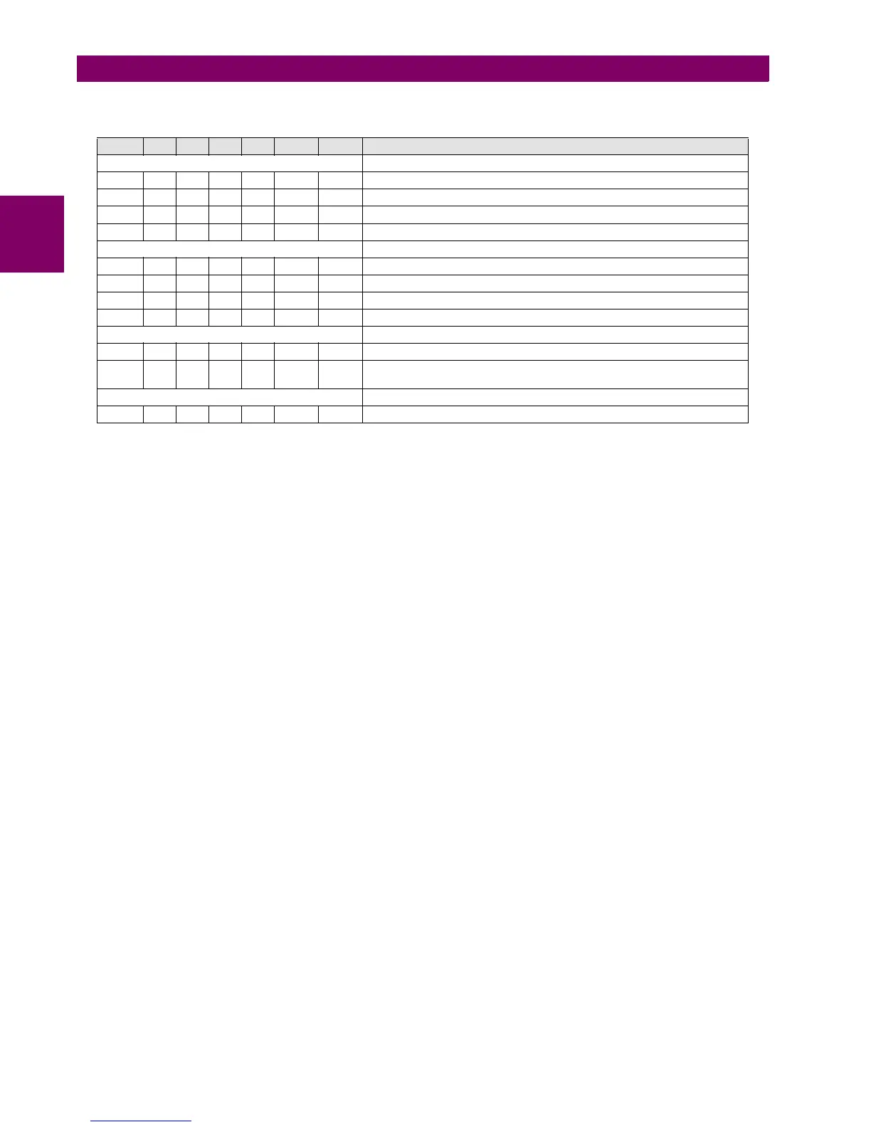
Table 2–2: ORDERING CODE FOR CIO MODULE
(1) The digit selected for option J must be equal or higher than the digit selected for option H for models including boards 4 and 5.
CIOH1J5**: is a valid selection CIOH5J1**: is an invalid selection
CIO H - J - - DESCRIPTION
I/O BOARD IN SLOT H
1 16 Digital inputs + 8 outputs
2 8 Digital Inputs + 8 Outputs + 2 trip/close circuit supervision circuits
4 32 Digital Inputs
5 16 Digital Inputs + 8 Analog Inputs
I/O BOARD IN SLOT J
0 None
1 16 Digital inputs + 8 outputs
4 32 Digital Inputs (See Note 1)
5 16 Digital Inputs + 8 Analog Inputs (See Note 1)
AUXILIARY VOLTAGE
LO 24-48 Vdc (range 19.2 – 57.6)
HI 110-250 Vdc (range 88 – 300)
120-230 Vac (range 96 – 250)
ENVIRONMENTAL PROTECTION
H Harsh (Chemical) Environment Conformal Coating
 Loading...


