GEK-106310AE F650 Digital Bay Controller 3-33
3 HUMAN INTERFACES. SETTINGS & ACTUAL VALUES 3.1 ENERVISTA 650 SETUP SOFTWARE INTERFACE
3
Table 3.22: DIFFERENT CONTROL ACTUAL VALUES INCLUDED IN THE CONTROL ELEMENTS MENU FOR
FIRMWARE VERSION 7.50 OR ABOVE
Table 3.23: ACTUAL VALUES RELATED TO RECORDING FUNCTIONS IN THE RECORDS STATUS MENU:
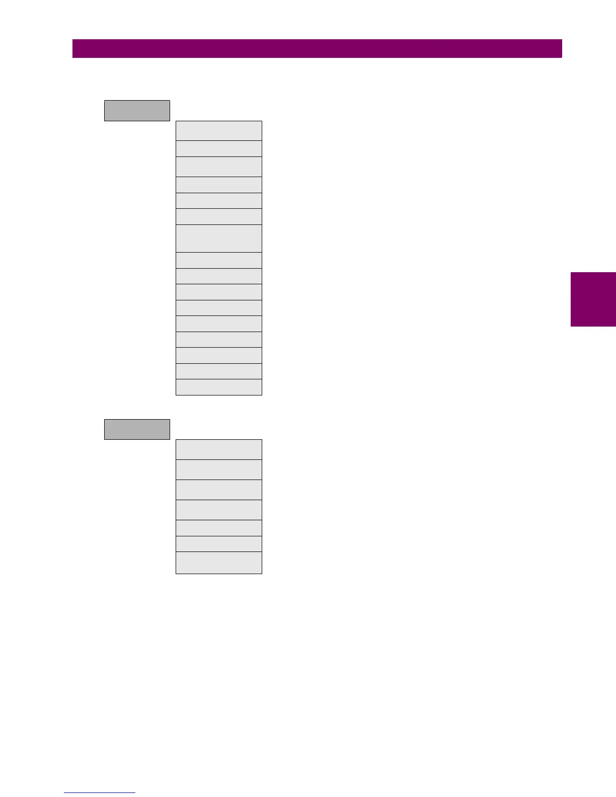
CONTROL
ELEMENTS
Frequency Status signals (pickups and operations) for under, overfrequency and
frequency rate of change units.
Synchrocheck Status signals for synchrocheck function (25).
Autoreclose Status signals for autoreclose function (79). Close signal, recloser status
(ready, lockout, etc.), block signals after each shot.
Breaker Failure Status signals for breaker failure function (50BF).
VT Fuse Failure Fuse failure detection signal.
Broken Conductor Status signals (pickups and operations) for broken conductor (I2/I1).
Setting Groups Status signals (activations and blocks) for the relay setting group change.
By default the "setting group" setting is disabled and all the grouped
elements can be enabled at the same time.
Locked Rotor Status signals (pickups and operations) for locked rotor units.
Pulse Counters Status signals for pulse counters units.
Analog Comparator Status signals for analog comparator units.
Load Encroachment Status signals (pickups and operations) for load encroachment units.
Max.Number of Starts Status signal for number of starts operations
Digital Counters Status signals for the Digital Counter units.
Cold Load Pickup Status signals for the Cold Load Pickup Function.
60 CTs failure Status signals of Current transformer failure Function
2nd HRMC Inhibit Status signals of Second Harmonic Inhibit Function
RECORD
STATUS
Fault Reports This menu shows the fault report status signals, as fault report trigger,
fault date, fault type and location, besides the fault report number.
Control Events Status of the control events (if the signal configured to launch the control
event is active or not).
Oscillography Status of signals related to oscillography recording, such as status or
digital channels, oscillography trigger, number of records available, etc.
Data Logger Data logger information about oldest and newest sample time stamp,
and number of channels and days configured in data logger settings.
Demand Demand trigger and reset inputs status.
Energy Freeze, unfreeze and reset input signals for energy counters.
Breaker Maintenance All signals related to breaker maintenance, such as number of openings,
closings, (KI)
2
t counters, alarm signal for (KI)
2
t, etc.

 Loading...


