41
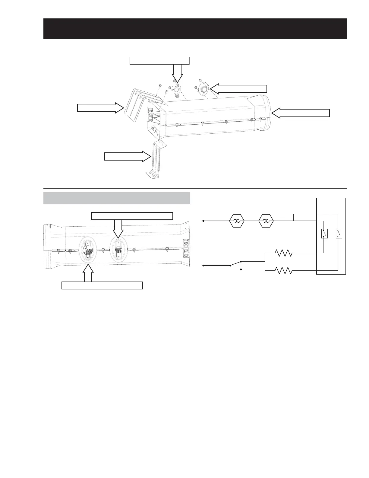
Electric Heating System
Heat er Assembly
Oper at i ng Volt age: 240 VAC
Resistanceű+HDWHU
Wattage: 3000 Wat ts / Heat er
Th e h eat er c on sist s of a n u p per c oi l an d a l ow er
coil. Normal heater cycling is controlled by the main
control board. The control board reads the inlet and
outlet thermistors to cycle the heaters. If a thermis-
tor fails, the heaters will be cycled by the inlet and
outlet thermostats. This may result in slightly less
HȻFLHQWRSHUDWLRQ
L2
Motor Centrifugal Swit ch
K4
Out l et Bac ku p
Th er m o st a t
L1
Intlet Backup
Th er m o st a t
J2
Bot tom Coil
To p Co i l
K3
Main Control
Boar d
J3
J8
J5
Heat er Removal
1. Disconnect water and power to the dryer.
2. Remove the control panel.
3. Remove the top panel.
Re m o v e t h e f r o n t p a n e l .
4. Remove the front control assembly bracket.
5. Remove the front drum support .
6. Remove the drum (see Drum Removal).
7. Disconnect the wire from the heater assembly.
8. Remove the two 1/4 in. hex screws that hold the
electric shield.
9. Remove the two 1/4 in. hex screws that hold the
heater assembly in place.
10. Remove the heater from the rear duct tab.
Heat Shield
Heater Bracket
High Limit Thermostat
Heater Assembly
Inlet Thermostat
High Limit Thermostat Location
Inlet Thermostat Location
See H ea t e r As s em b l y Lo c a t i o n o n p a g e 17 .
See Co n t r o l Pa n e l Rem o v a l o n p a g e 2 0 .
See To p Pa n el Rem o v a l o n p a g e 24 .
See Fr o n t Pa n e l Re m o v a l o n p a g e 2 4 .
See Fr o n t Co n t r o l As s em b l y Br a c k et Rem o v a l
on page 25.
See Fr o n t D r u m Su p p o r t Rem o v a l o n p a g e 34 .