44
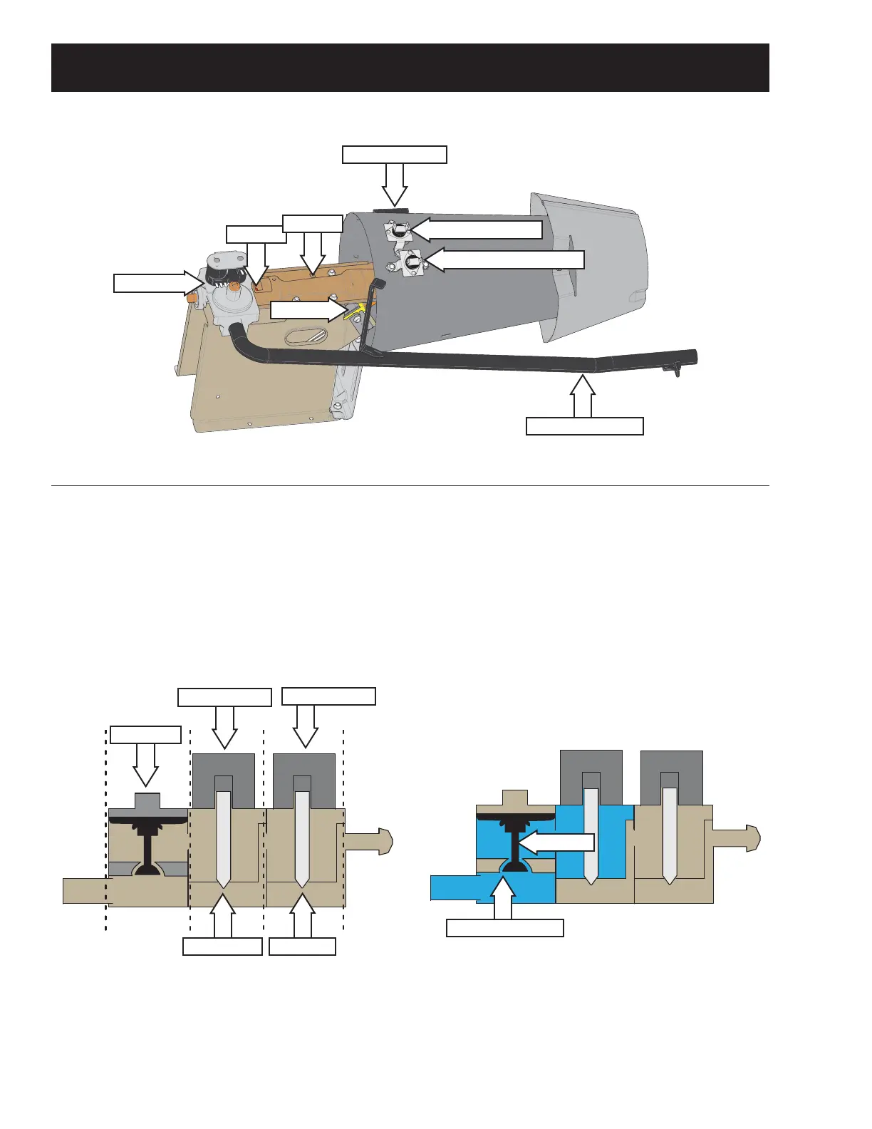
Gas Heating System
2UL¿FH
Gas Supply Pipe
Igniter
Burner
Gas Valve
Inlet Thermostat
High Limit Thermostat
Gas Flow
*DVÀRZWRWKHEXUQHULVFRQWUROOHGE\WKHJDVYDOYH
assembly. The gas valve assembly consists of a
regulator, safety valve, main valve and solenoids to
operate the gas valves. See below.
Gas Va l ve Bl ock Di ag r a m
Regulator
Safety Valve
Main Valve
Dual Solenoid
Single Solenoid
Th e d ua l so len oi d co nsi st s o f a sa f et y co il a nd a
booster coil. To ensure safe operation, both coils
must be energized in order to open the safety valve.
As gas ent ers t he gas valve assembly, t he regulat or
DQGVDIHW\YDOYHFKDPEHUV¿OOZLWKJDVDVVKRZQLQ
WKHVKDGHGDUHDLQWKH¿JXUHEHORZ
Th e r eg ul at o r r egu l at es g a s p r essu r e b y m o vi ng a n
actuator up and down as needed. When the gas
pressure goes too high, the excess pressure in the
regulator chamber forces the actuator to rise. This
FORVHVRȺWKHJDVHQWU\SRUW$VWKHJDVSUHVVXUH
lowers, the port opens back up.
Re g u l a t o r a n d Sa f e t y Ch a m b e r
Actuator
Gas Entry Port
Flame Detector