43
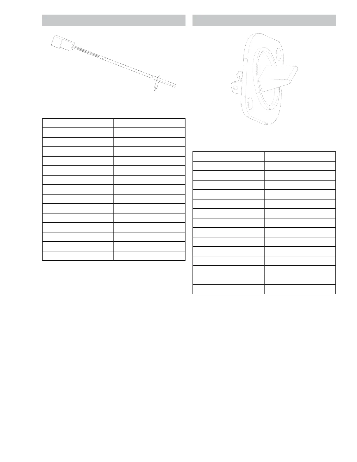
Inlet Thermistor
Inlet Thermistor Chart
Temperature Resistance
50.0°F Nű
70.7°F Nű
75.2°F Nű
80.6°F Nű
85.1°F Nű
90.5°F Nű
95.9°F Nű
100.4°F Nű
105.8°F Nű
110.3°F Nű
115.7°F Nű
120.2°F Nű
150.8°F Nű
200.3°F Nű
Inlet Thermistor Removal
1. Disconnect power from the unit .
2. Remove the control panel.
3. Remove the top panel.
4. Remove the rear panel.
5. Remove the inlet thermistor wires.
6. Remove the 1/4 in. hex screws that hold the inlet
thermistor to the rear duct.
Out let Ther mi st or
Outlet Thermistor Chart
Temperature Resistance
50.0°F Nű
69.8°F Nű
75.2°F Nű
80.6°F Nű
86.0°F Nű
89.6°F Nű
95.0°F Nű
100.4°F Nű
105.8°F Nű
111.2°F Nű
116.6°F Nű
120.2°F Nű
149.0°F Nű
199.4°F Nű
Out let Thermist or Removal
1. Disconnect power from the unit .
2. Remove the drum.
3. Remove the outlet thermistor wires.
4. Remove the two 1/4 in. hex screws that hold the
outlet thermistor to the blower housing.
See I n l e t Th e r m i s t o r Lo c a t i o n o n p a g e 19 .
See Co n t r o l Pa n e l Rem o v a l o n p a g e 2 0 .
See To p Pa n el Rem o v a l o n p a g e 24 .
See Re a r Pa n el Rem o v a l o n p a g e 26 .
See Ou t l e t Th e r m i s t o r Lo c a t i o n o n p a g e 17 .
See D r u m Rem o v a l o n p a g e 35 .