50
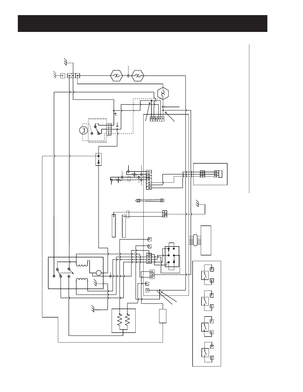
Schematic
Rear Panel
DSM Board
J1
1 2 3 4 5 6
J4
1 2 3 4 5 6 7
TCO
Start
Run
Drum Motor- Stopped
Bottom Coil
Top Coil
Steam
Valve
J14
1 2 3 4
J8
J5
N
L1
J203
RJ45
J202
3 2 1
Dryer Main Control Board
Idler/Belt Break SW –
Shown Intact
Cent. SW
G
L1
L2
240 VAC Power In TB
Inlet
TH
Outlet
TH
Outlet Backup
Thermostat
Inlet Backup
Thermostat
Hi-Limit
Thermostat
Com
Door Switch
Shown Door
Closed
N.O.
N.C.
L1
N
HA Dryer UI
(Direct Wire Connections to Main
MC Board)
1
2
5
6
3
4
K7
Drum
Reverse
8 7 1
1 2
J9
1 2 3
J7
(Main 1)
(AUX 1)
(AUX 2)
4
9
5
7
8
1
2
6
3
(Main 2)
In
In
In
Out
Out
Out
1
2
COM N.O.
12
1
1
2
2
UI Panel
GND
COM
Frame
A
B
GND (4 Wire System) Only
(Rear Panel)
GND (3 Wire System)
Brass Bar To Chassis
(Neutral Not Grounded)
L2
COM
COM
NO
NO
NC
InLine
Conn.
InLine Conn.
1 2 3
12-Black
16-White
18-Black/Yellow
20-Gray
20-Red
20-Violet
12-Violet
20-Aqua
18-White/Violet
20-Orange/White
20-Aqua
14-Green
16-White
18-Orange/White
12-Aqua
20-Pink
20-Green
12- Violet/Red
18-Navy/White
18-Tan/Red
18-Yellow
18-Brown
18-Black/Red
18-White/Red
12-Violet/Yellow
18-Black/Yellow
18-Black
22-Navy
22-Yellow
22-Orange
14-Orange/Black
18-Pink/Black
18-Black/Orange
Splice (20-White)
12-Gray/Red
K1 – Motor
J6-2 J6-3
K2 – Steam
J6-2
J6-1
K4 – Bottom Coil
J3 J2
K3 – Top Coil
J8 J5
PCB Relay Detail Insert
18-White/Red
Base
1 2 3
Splice
(InLine
Connector)
Splice
(K3)
J3
J2
(K4)
See PCB Relay
Detail Insert
20-Navy
20-Navy
20-Violet
20-Red
Incand. Drum Lamp
(See Note 1)
Upper Rod
Lower Rod
J6
1 2 3
(K1,K2)
18-Black18-White
18-White
18-Yellow
14-White/Red
1
2
Note 1: Wire Shown “DASHED” Is
Only On Models With Incandescent
Drum Lamp. LED Drum Lamp Not
Included On Those Models.
LED
Drum
Lamp
_
+
Red
Black
Certain Models Only.
See Note 1.
Splice
14-Orange/Black
14-Orange/Black
(Located In Main Bundle
Appx 10 Inches From J2)
WIRING SCHEMATIC FOR ELECTIC DRYER MODELS: