EasyManuals Logo

GE LOGIQ E9 Service Manual

GE LOGIQ E9
808 pages
To Next Page IconTo Next Page
To Previous Page IconTo Previous Page
Page #209 background imageLoading...
Page #209 background image
GE
D
IRECTION 5535208-100, REV. 2 LOGIQ E9 SERVICE MANUAL
Chapter 5 Components and Functions (Theory) 5 - 11
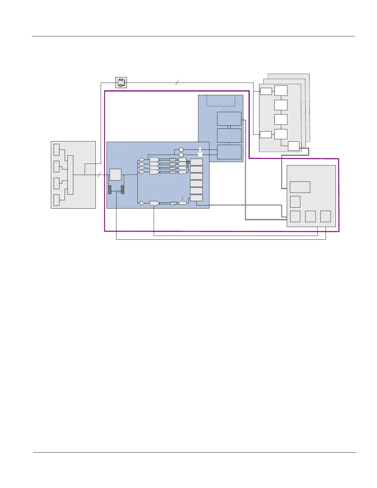
5-2-7 Signal flow overview (cont’d)
The MRX Board combines the functionality of the Receiver Boards (DRX and GRX) and the GFI.Weak
ultrasound echoes from body structures and blood cells are received by the probes and routed via the
Relay board and the XD bus to the MRX board. The MRX board amplifies the ultrasound signal and
connects it with an A/D converter to the digital domain. The digital signals are then further processed
on the MRX boards.
Figure 5-6 LOGIQ E9 Signal Flow
- MRX
GTX 64 Ch
GTX
64 Ch
GTX 64 Ch
256
256
MRX
Frontplane
GRLY
256
R
e
l
a
y
s
192
192
192
GDIF
David
1
David
2
Pulser
David
3
Pulser
...
David
0
T/ R
A/D
A/DA
Nathan
32 Ch
TGC
TGC
TGC
TGC
TGC
X
Nathan
32 Ch
Nathan
32 Ch
Nathan
32 Ch
Nathan
32 Ch
Nathan
32 Ch
MRX 192 Ch
X
I
CW
Option
Analog
Beamformer
Filter
A/D
Converters
I / Q
Front End
Interface
GFE
SED
DSP
Test
Gen
TGC
Gen
X
A/DA
A/DA
A/DA
Q

Table of Contents

Other manuals for GE LOGIQ E9

Questions and Answers:

Question and Answer IconNeed help?

Do you have a question about the GE LOGIQ E9 and is the answer not in the manual?

GE LOGIQ E9 Specifications

General IconGeneral
TypeUltrasound System
3D/4D ImagingYes
Transducer Ports4 active ports
ConnectivityDICOM, USB, Ethernet
ApplicationsAbdominal, Vascular, Musculoskeletal, Small Parts, Urology, Pediatric, Cardiac, Obstetrics/Gynecology
TransducersLinear, Convex, Phased Array, Volume
Doppler ModesColor Doppler, Power Doppler, Pulsed Wave Doppler, Continuous Wave Doppler
ElastographyYes
Advanced FeaturesB-Flow, Volume Navigation
PortabilityCart-based system
Display19-inch high-resolution LCD monitor

Related product manuals