GE
D
IRECTION 5535208-100, REV. 2 LOGIQ E9 SERVICE MANUAL
8 - 218 Section 8-9 - BEP (Back End Processor) parts replacement
8-9-4-1 BEP I/O Board removal
Table 8-131 BEP I/O Board removal
Steps Corresponding Graphic
1.
Loosen the thumb screw or screws at the top of the BEP cover that attach the cover to the BEP.
Tilt the top of the BEP cover away from the BEP.
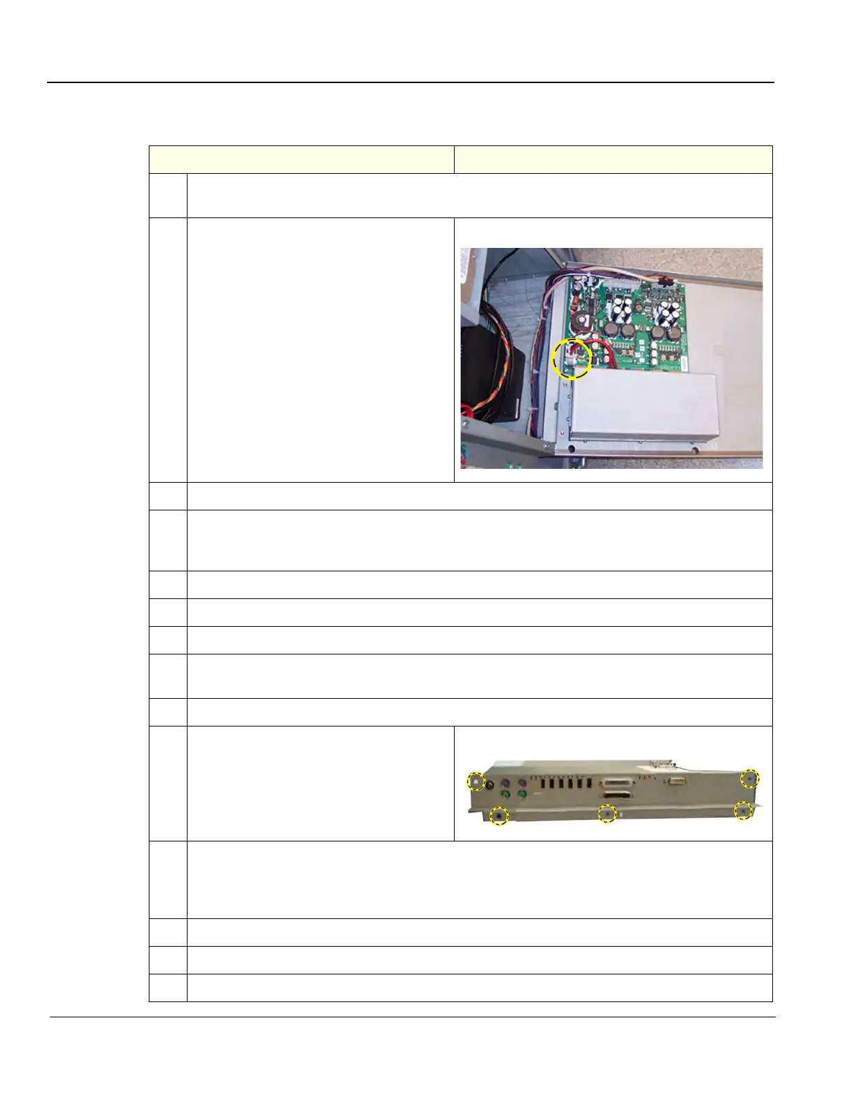
2.
Disconnect the battery cable connecting to
J3 on the EPS.
EPS Battery connection (J3)
3.
Disconnect the cables inside the BEP that connect to the I/O.
4.
Remove the HDD. See: 8-9-6-2 "HDD installation" on page 8-229.
NOTE: DO NOT forget to remove the metal tabs holding the cables to the Hard Drive.
5.
Remove all cables connected to the I/O Board and the Option Dongle.
6.
Remove the plug from J35 connector on the I/O Board.
7.
Remove the cable from J36. Squeeze from the base of the connector to release the cable.
8.
Remove the plug from J20 by grabbing the metal connector (not the flex cable) and wiggling to
gently remove.
9.
Remove J46 network cable. Remember to release the tab to disconnect.
10.
Remove the five screws connecting the I/O
to the BEP.
BEP I/O Board screw placement
11.
Gently slide the I/O Board out. Be careful to allow room for external connectors to slip past the
back of the BEP.
NOTE: Remember there is still a connected cable at the base of the I/O Board.
12.
Slide out the I/O Board approximately 2 inches.
13.
Gently tip out the top of the I/O Board.
14.
Carefully remove the I/O Board until you can access the connector labeled J34.