5-134 M60 MOTOR PROTECTION SYSTEM – INSTRUCTION MANUAL
PRODUCT SETUP CHAPTER 5: SETTINGS
5
DIRECT OUTPUT DEVICE ID: “1”
DIRECT I/O CH1 RING CONFIGURATION: “Yes”
DIRECT I/O DATA RATE: “128 kbps”
For UR-series IED 2:
DIRECT OUTPUT DEVICE ID: “2”
DIRECT I/O CH1 RING CONFIGURATION: “Yes”
DIRECT I/O DATA RATE: “128 kbps”
The message delivery time is about 0.2 of power cycle in both ways (at 128 kbps); that is, from device 1 to device 2, and
from device 2 to device 1. Different communications cards can be selected by the user for this back-to-back connection
(for example: fiber, G.703, or RS422).
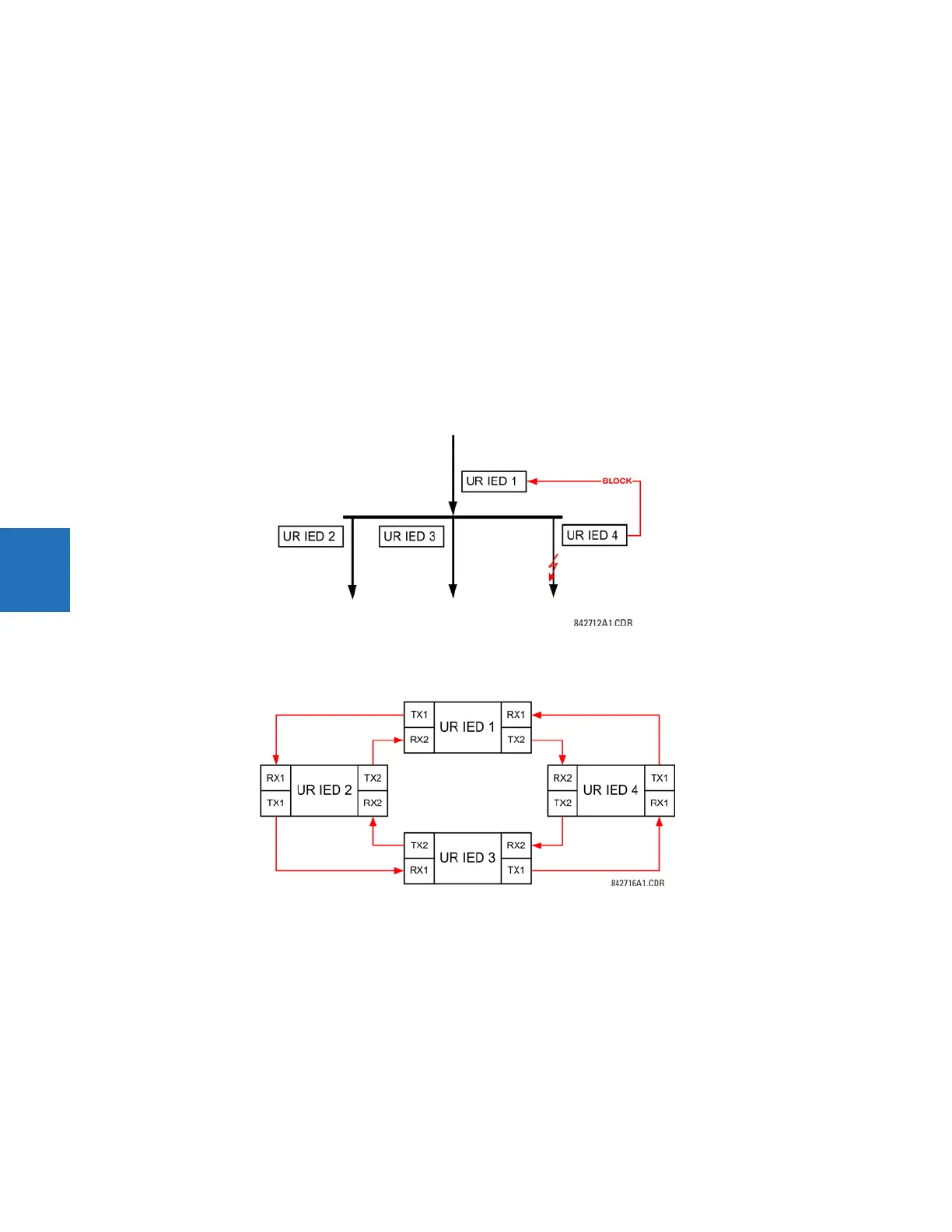
Example 2: Interlocking busbar protection
A simple interlocking busbar protection scheme could be accomplished by sending a blocking signal from downstream
devices, say 2, 3, and 4, to the upstream device that monitors a single incomer of the busbar, as shown.
Figure 5-60: Sample interlocking busbar protection scheme
For increased reliability, a dual-ring configuration (shown as follows) is recommended for this application.
Figure 5-61: Interlocking bus protection scheme via direct inputs/outputs
In this application, apply the following settings. For UR-series IED 1:
DIRECT OUTPUT DEVICE ID: “1”
DIRECT I/O CH1 RING CONFIGURATION: “Yes”
DIRECT I/O CH2 RING CONFIGURATION: “Yes”
For UR-series IED 2:
DIRECT OUTPUT DEVICE ID: “2”
DIRECT I/O CH1 RING CONFIGURATION: “Yes”
DIRECT I/O CH2 RING CONFIGURATION: “Yes”
For UR-series IED 3: