5-206 M60 MOTOR PROTECTION SYSTEM – INSTRUCTION MANUAL
GROUPED ELEMENTS CHAPTER 5: SETTINGS
5
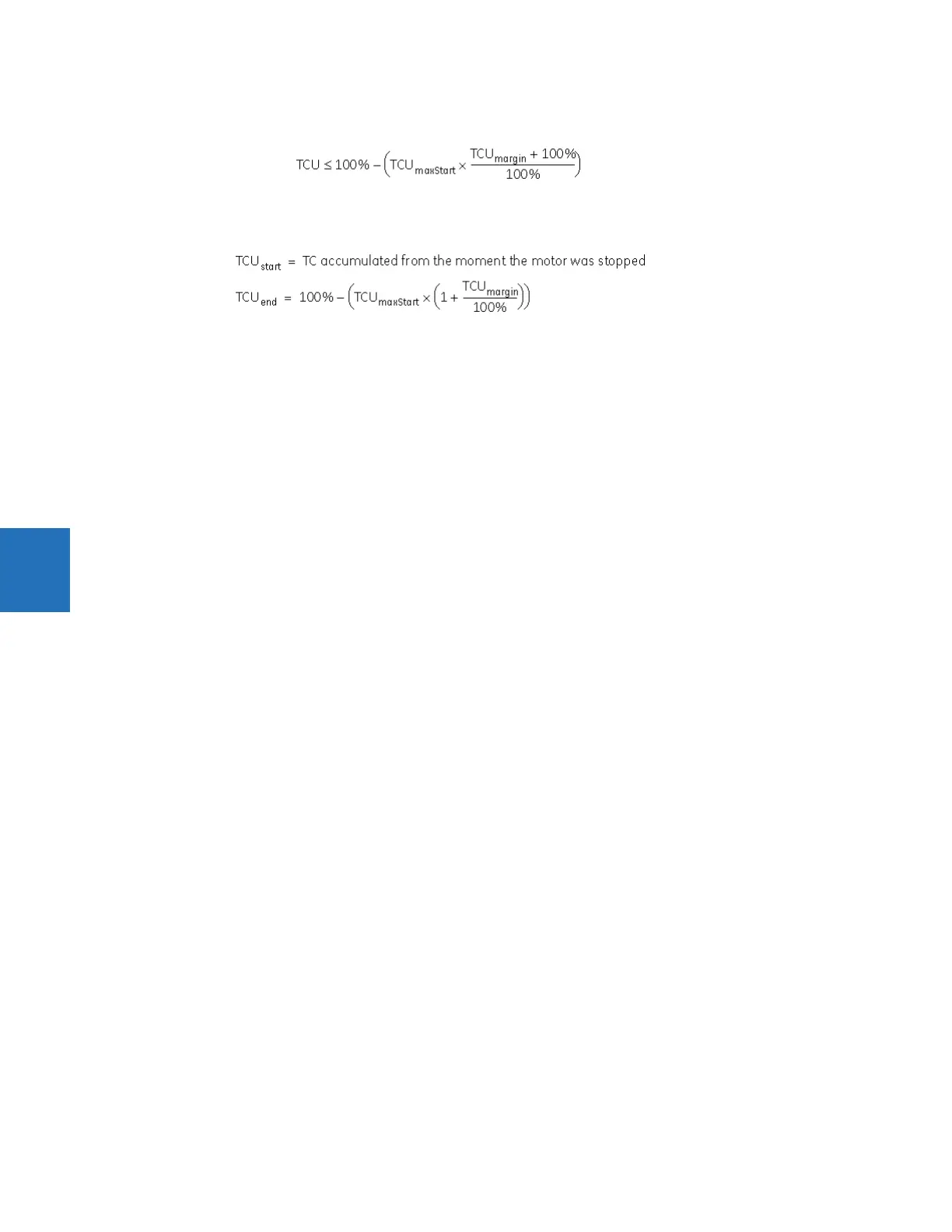
In this case, the MOTOR START INHIBIT operand resets when TCU decays to the level satisfying the following equation.
Eq. 5-22
To calculate the thermal lockout time for the case when the MOTOR START INHIBIT MARGIN setting is greater than “0,” the
following TCU values are applied.
Eq. 5-23
If MOTOR START INHIBIT MARGIN is greater than “0,” but the relay does not contain records for five successful starts, then the
MOTOR START INHIBIT operand can be asserted again either when the motor is tripped by thermal protection (TCU = 100%) or
tripped/stopped by any other reason (TC
accumulated
< 100%). However, operand reset is evaluated based on 15% level of
thermal capacity. To calculate the thermal lockout time in this case, the following values of TCU are applied to the previous
equation: TCU
start
= thermal capacity accumulated from the moment the motor was stopped, and TCU
end
= 15%.
VOLTAGE DEPENDENT FUNCTION — If the motor is called upon to drive a high inertia load, it is quite possible and acceptable
for the acceleration time to exceed the safe stall time (keeping in mind that a locked rotor condition is different than an
acceleration condition). The voltage dependent overload curve feature is tailored to protect these types of motors. This
curve is composed of the three characteristic of thermal limit curve shapes as determined by the stall or locked rotor
condition, acceleration, and running overload. The following figure presents the typical thermal limit curve for high inertia
application.