CHAPTER 5: SETTINGS GROUPED ELEMENTS
M60 MOTOR PROTECTION SYSTEM – INSTRUCTION MANUAL 5-207
5
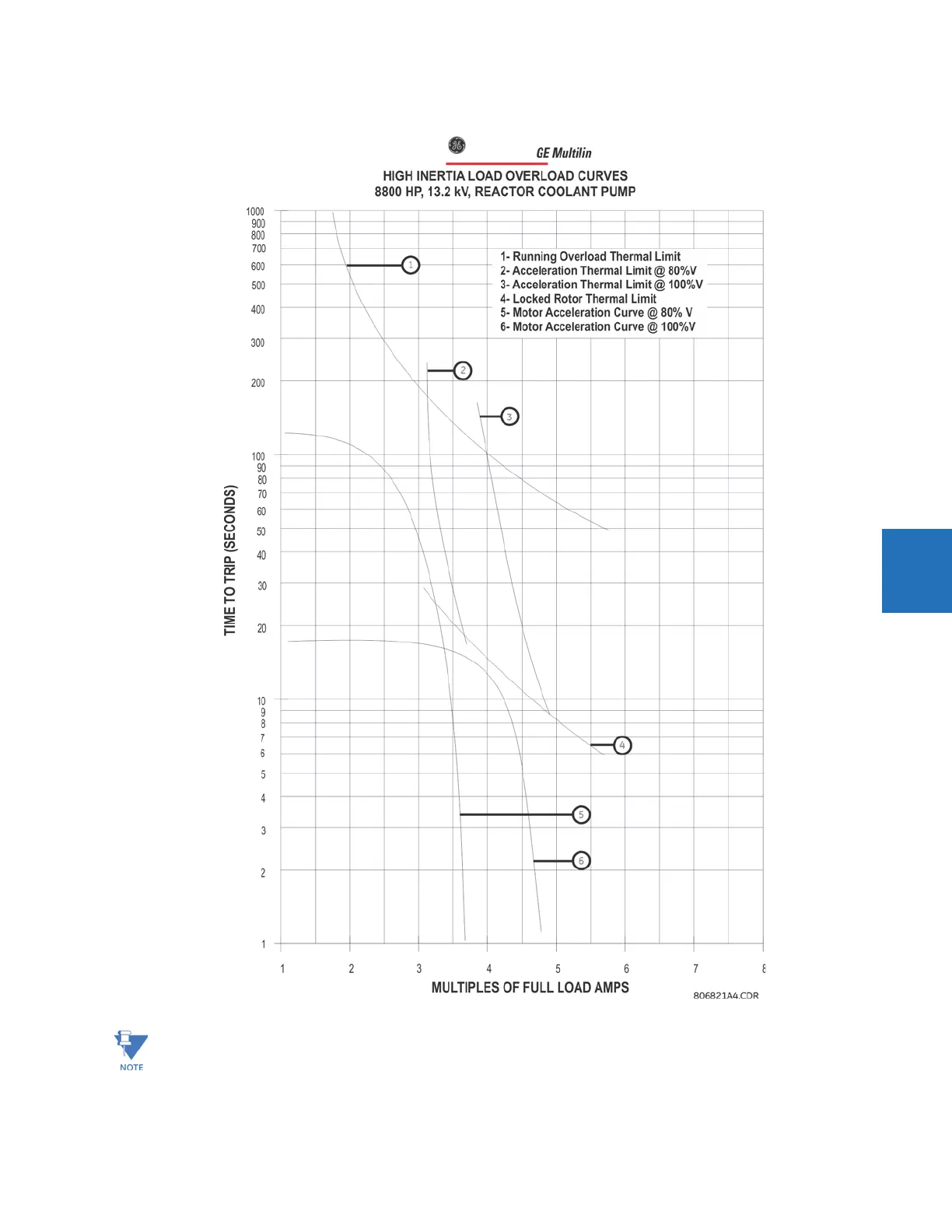
Figure 5-106: Thermal limit curve for high inertia
TVoltage dependent overload functionality is operational only if the selected
MOTOR LINE SOURCE in the SYSTEM
MOTOR SETUP
menu is assigned to a valid three-phase VT.