5-210 M60 MOTOR PROTECTION SYSTEM – INSTRUCTION MANUAL
GROUPED ELEMENTS CHAPTER 5: SETTINGS
5
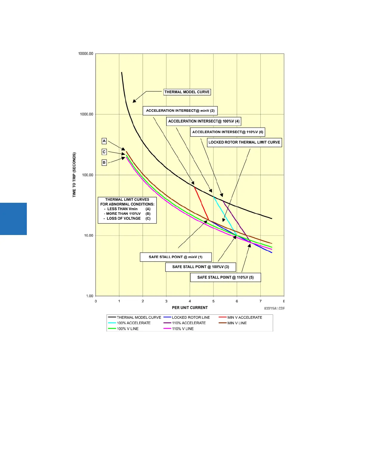
Figure 5-108: Voltage dependent overload curves
This figure and the following procedure illustrate the construction of the voltage overload curves.
1. Draw a curve for the running overload thermal limit. The curve is one that has been selected in the relay as a
THERMAL
MODEL CURVE
.
2. Determine the point of intersection between the
THERMAL MODEL CURVE and the vertical line corresponding to the per-
unit current value of
VD ACCEL. INTERESECT @ MIN V (see point 2).
3. Determine the locked rotor thermal limit point for the minimum voltage motor start. The coordinates of this point are
the per-unit current value of
VD STALL CURRENT @ MIN VOLTS and the time value of VD SAFE STALL TIME @ MIN V (see point
1).
4. The line connecting points 1 and 2 constructs the acceleration curve for the system voltage level defined by the
VOLTAGE DEPENDENT MIN MOTOR VOLTS setting. The acceleration time-current curve for the minimum voltage starting