CHAPTER 5: SETTINGS GROUPED ELEMENTS
M60 MOTOR PROTECTION SYSTEM – INSTRUCTION MANUAL 5-211
5
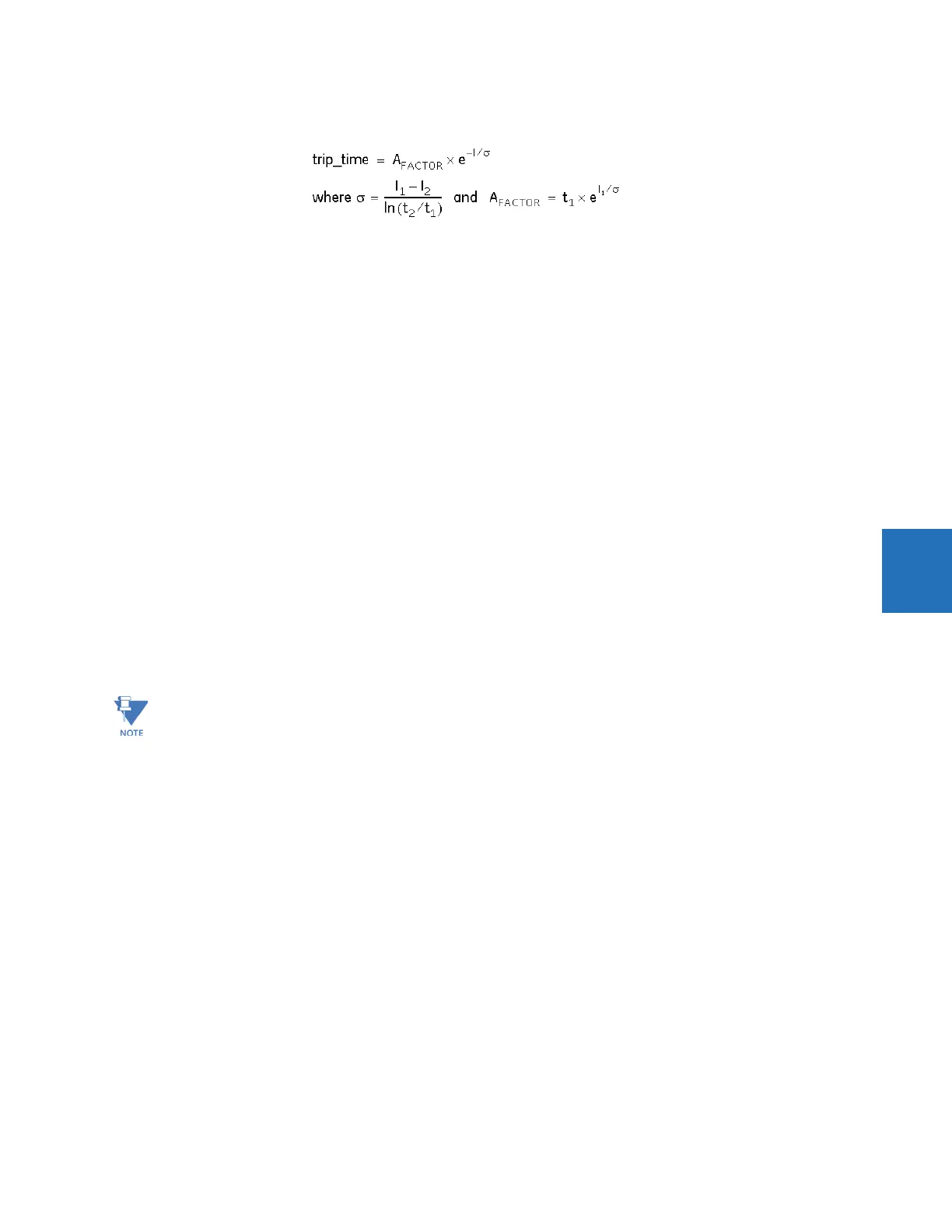
is calculated from the following equation.
Eq. 5-26
where
I is a variable multiplier of the motor rated current (values between I
1
and I
2
)
I
1
is a multiplier of the rated motor current (FLA) specified by the VD STALL CURRENT @ MIN V setting
t
1
is a time value specified by the VD SAFE STALL TIME @ MIN V setting
I
2
is a multiplier of the rated motor current (FLA) specified by the VD ACCEL. INTERESECT @ MIN V setting
t
2
is a time coordinate of the intersection point between the thermal model curve and the vertical line corresponding
to the per-unit current value of the
VD ACCEL. INTERESECT @ MIN V setting
5. Determine the point of intersection between the thermal model curve and the vertical line corresponding to the
multiplier of the rated current value of the
VD ACCEL. INTERESECT @ 100% V setting (see point 4).
6. Draw the locked rotor thermal limit point for the 100% voltage motor start. The coordinates of this point are the
multiplier of the rated current value (FLA) of the
VD STALL CURRENT @ 100% V setting and the time value of the VD SAFE
STALL TIME @ 100% V
setting (see point 3).
7. The line connecting points 3 and 4 constructs the acceleration curve for the motor rated system voltage. The
acceleration time-current curve for the rated voltage starting is calculated from the same equations, but the setpoints
associated with the 100% voltage starting are applied.
8. The line connecting points 1, 3, and 5 represent the motor safe stall conditions for any system voltage from the
minimum to 110% of rated. Ideally, all the points on this line are characterized by the same thermal limit (I
2
t), but the
equivalent starting impedance at reduced voltage is greater than the impedance at full voltage. As such, the higher
terminal voltages tend to reduce I
2
t. The rate of I
2
t reduction is dictated by the VD STALL CURRENT and VD SAFE STALL
TIME
setpoints for rated and minimum voltage conditions. For voltage conditions above rated, the locked rotor
thermal limit and acceleration curve are extrapolated up to 110% of the terminal voltage. The point coordinates (I
s
, T
s
)
for 110% are extrapolated based on the I
1
, T
1
, I
3
, and T
3
values. For starting currents at voltages higher than 110%, the
trip time computed from 110% V thermal limit value will be used.
The following three figures illustrate the resultant overload protection curve for minimum, 100%, and maximum line
voltages. For voltages between these limits, the M60 shifts the acceleration curve linearly and constantly, based on the
measured line voltage during a motor start.
The voltage dependent curve for current values above 1.1 x VD STALL CURRENT @ 100% V are clamped and the
time to trip is frozen at the level calculated for the 8 times pickup current.