CHAPTER 5: SETTINGS GROUPED ELEMENTS
M60 MOTOR PROTECTION SYSTEM – INSTRUCTION MANUAL 5-215
5
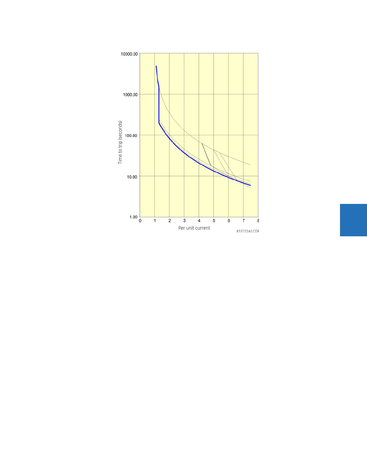
Figure 5-114: Voltage dependent overload curve protection at more than 110% voltage
For the three abnormal voltage situations, the M60 makes a transition from the acceleration curve to Motor or FlexCurve
when the MOTOR RUNNING or MOTOR OVERLOADED operands are asserted.