5-218 M60 MOTOR PROTECTION SYSTEM – INSTRUCTION MANUAL
GROUPED ELEMENTS CHAPTER 5: SETTINGS
5
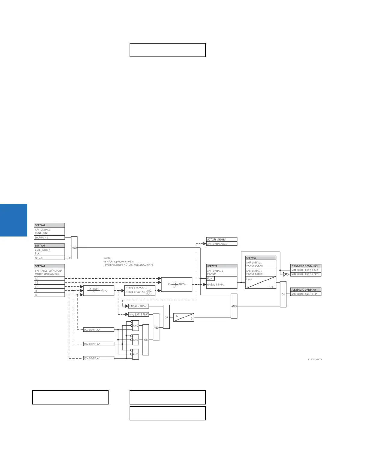
This element receives current inputs from the source selected by the SETTINGS SYSTEM SETUP MOTOR MOTOR
LINE SOURCE
setting. Generally, this element compares the ratio of motor negative sequence current (I_2) to the positive
sequence current (I_1) times an adjustment factor to compensate for the actual motor load to a set threshold. The
adjustment factor is used to prevent nuisance alarms at light loads. If the motor is operating at an average current level
equal to or greater than the programmed full load current (FLA, as selected by the
SYSTEM SETUP MOTOR MOTOR
FULL LOAD AMPS
setting) the adjustment factor is one. If the motor is operating at an average current level less than the
programmed full load current (as selected by the
SYSTEM SETUP MOTOR MOTOR FULL LOAD AMPS setting) the
adjustment factor is the ratio of average current to full load current. It is intended that the Amp Unbalance 1 element is
used to generate an alarm and Amp Unbalance 2 element is used to generate a trip.
A declaration of a “single-phasing” condition is made two seconds after the unbalanced current level exceeds 40%, or the
average current is above 25% of FLA and the current in any one phase is less than 2% of FLA.
AMP UNBAL 1(2) PICKUP — This setting selects the level of unbalanced current that generates a stage 1 (intended to alarm)
output. Note that a supply voltage unbalance of 1% creates a current unbalance of 6% in a typical three-phase induction
motor; a supply voltage unbalance of 2% creates a current unbalance of 12%. As a 2% voltage unbalance is common in
most applications, a setting of 0.15 is often used as the alarm level, and
AMP UNBAL 1 PICKUP is usually set to this level or
higher.
AMP UNBAL 1(2) PICKUP DELAY — The alarm delay is often set from 5 to 10 seconds. A higher level of unbalance causes
motor stress in a shorter period; a reasonable setting is 3 to 10 seconds.
AMP UNBAL 1(2) RESET DELAY — This timer can be used to maintain the output until other equipment or an operator can
react to the unbalance condition.
Figure 5-117: AMP unbalance logic
5.7.3.5 Mechanical jam
SETTINGS GROUPED ELEMENTS SETTING GROUP 1(6) MOTOR MECHANICAL JAM
AMP UNBAL 1 EVENTS:
Disabled
Range: Disabled, Enabled
MECHANICAL JAM
MECHANICAL JAM
FUNCTION: Disabled
Range: Disabled, Enabled
MECH JAM OVERCURRENT
PICKUP: 2.00 x FLA
Range: 1.00 to 10.00 x FLA in steps of 0.01