CHAPTER 6: ACTUAL VALUES METERING
M60 MOTOR PROTECTION SYSTEM – INSTRUCTION MANUAL 6-17
6
This menu displays the metered values available for each source.
Metered values presented for each source depend on the phase and auxiliary VTs and phase and ground CTs assignments
for this particular source. For example, if no phase VT is assigned to this source, then any voltage, energy, and power
values are unavailable.
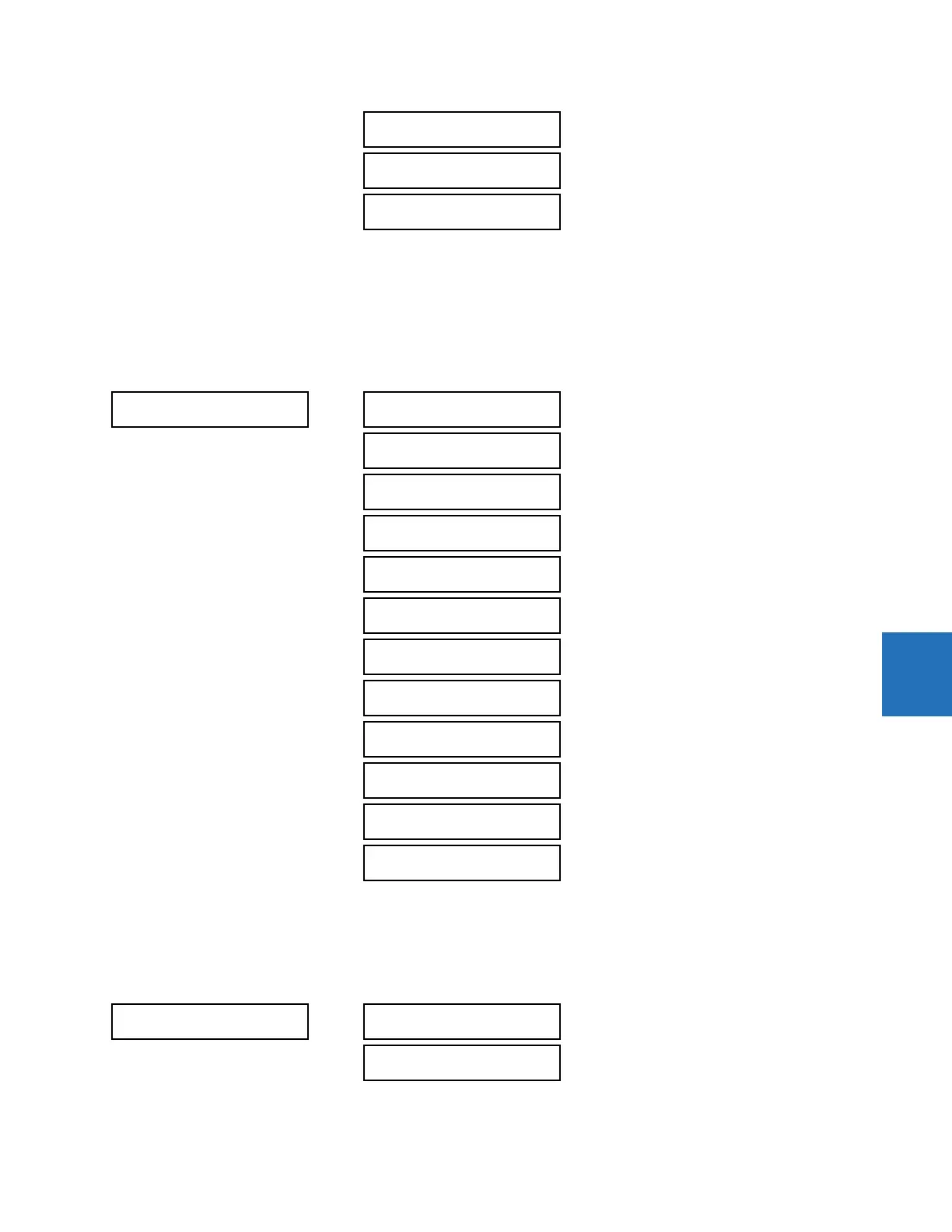
6.4.4.2 Phase current metering
ACTUAL VALUES METERING SOURCE SRC 1 PHASE CURRENT
The metered phase current values are displayed in this menu. The "SRC 1" text gets replaced by whatever name was
programmed by the user for the associated source (see
SETTINGS SYSTEM SETUP SIGNAL SOURCES).
6.4.4.3 Ground current metering
ACTUAL VALUES METERING SOURCE SRC 1 GROUND CURRENT
POWER
SRC 1
See page 6-19
ENERGY
SRC 1
See page 6-20
FREQUENCY
SRC 1
See page 6-20
PHASE CURRENT
SRC 1
SRC 1 RMS Ia: 0.000
b: 0.000 c: 0.000 A
SRC 1 RMS Ia:
0.000 A
SRC 1 RMS Ib:
0.000 A
SRC 1 RMS Ic:
0.000 A
SRC 1 RMS In:
0.000 A
SRC 1 PHASOR Ia:
0.000 A 0.0°
SRC 1 PHASOR Ib:
0.000 A 0.0°
SRC 1 PHASOR Ic:
0.000 A 0.0°
SRC 1 PHASOR In:
0.000 A 0.0°
SRC 1 ZERO SEQ I0:
0.000 A 0.0°
SRC 1 POS SEQ I1:
0.000 A 0.0°
SRC 1 NEG SEQ I2:
0.000 A 0.0°
GROUND CURRENT
SRC 1
SRC 1 RMS Ig:
0.000 A
SRC 1 PHASOR Ig:
0.000 A 0.0°