Chapter 1. Installation
4 PanaFlow™ XMT1000 User’s Manual
1.4.1 Access to the Meter (cont.)
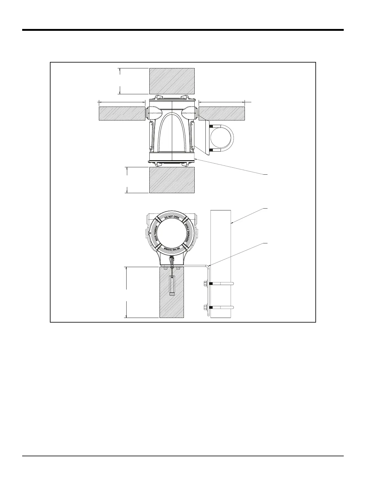
Figure 3: XMT1000 Enclosure Clearances (ref. dwg. 712-2164)
1.4.2 Vibration Exposure Considerations
Whenever possible, install the XMT1000 flow transmitter in a location isolated from vibrations. Avoid installing it near
equipment that generates low-frequency, high-energy random vibrations.
1.4.3 Sunlight Exposure
The installer should consider and limit exposure of the XMT1000 flow transmitter to direct sunlight. Sunshades should
be utilized in extreme environments.
1000 SERIES ELECTRONICS
12 in. (300 mm) CLEARANCE
MINIMUM RECOMMENDED
FOR CABLE ENTRY
12 in. (300 mm) CLEARANCE
MINIMUM RECOMMENDED
FOR CABLE ENTRY
12 in. (300 mm) CLEARANCE
MINIMUM RECOMMENDED
FOR SERVICE ACCESS
12 in. (300 mm) CLEARANCE
MINIMUM RECOMMENDED
FOR SERVICE ACCESS
12 in. (300 mm) CLEARANCE
MINIMUM RECOMMENDED
FOR CABLE ENTRY
CUSTOMER SUPPLIED 2” PIPE
1000 SERIES
REMOTE MOUNT KIT

 Loading...


