Handling and assembly
Axle assembly
2018-9015-001
09-2016
44 / 192
5.5.6 Knuckle connection
9
10
1
2
3
4
5
6
7
8
8
A
8
8
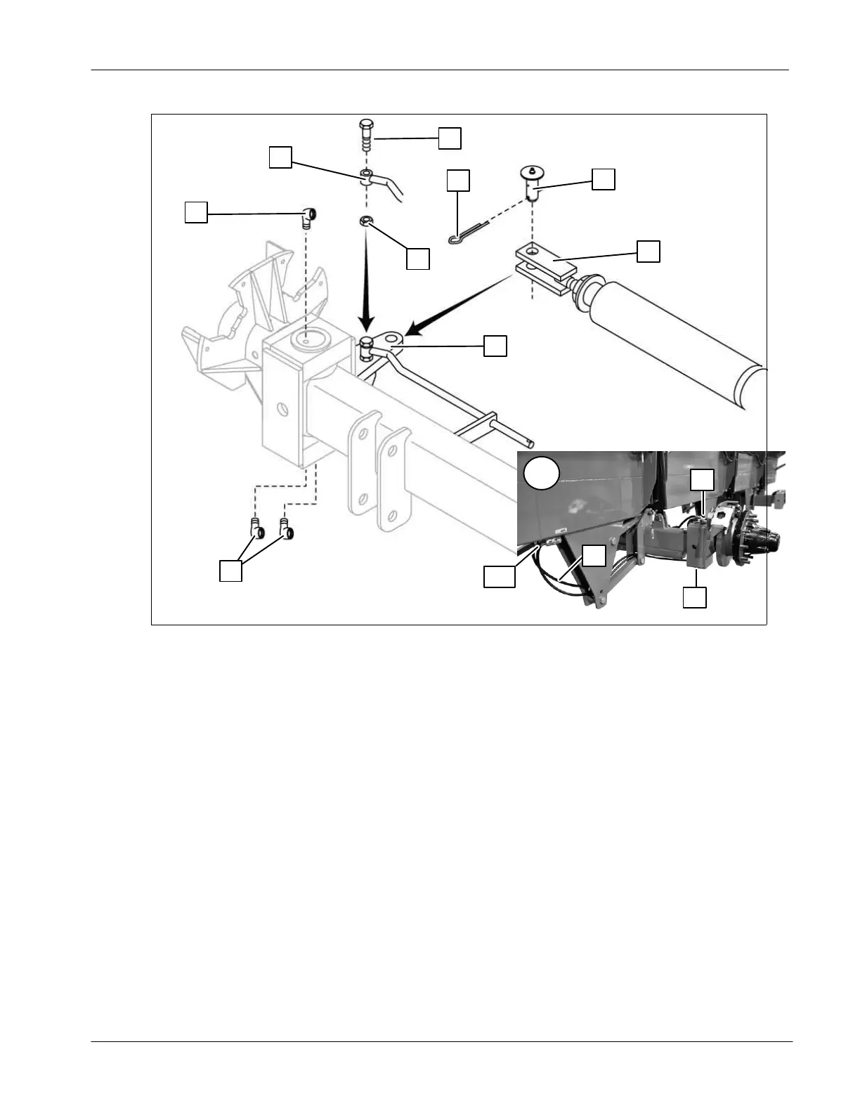
● Insert the bolt (1) in the connecting rod (2). Screw the jam nut (3) on the bolt
(1), keep a space between the nut (3) and the connecting rod (2);
● Bolt the assembly in the steering knuckle side plate (4) until the jam nut (3)
touches the side plate (4);
● Using two keys, hold the jam nut (3) and adjust the bolt (1) to keep a space
of 1/16” [1 mm] between the parts. It allows the rod to pivot freely;
● Once adjusted, hold the bolt (1) and tighten the jam nut (3) against the side
plate (4);
● Connect the clevis (5) on the knuckle side plate (4) using a hinge pin (6).
Lock the hinge pin (6) using a cotter pin (7);
● Apply Teflon tape on the fittings threads (8);
● Screw one fitting (8) on top of the pivot shaft and two fittings (8) underside.
Make sure the fittings point toward the center of the spreader;
● Connect the grease lines (9) from the fittings (8) to the hose brackets (10)
as shown in Detail A;
● Repeat these steps for each knuckle.