assembly and installation
Electrical Installation
7160-9001-560
01. December 2020
24 / 74
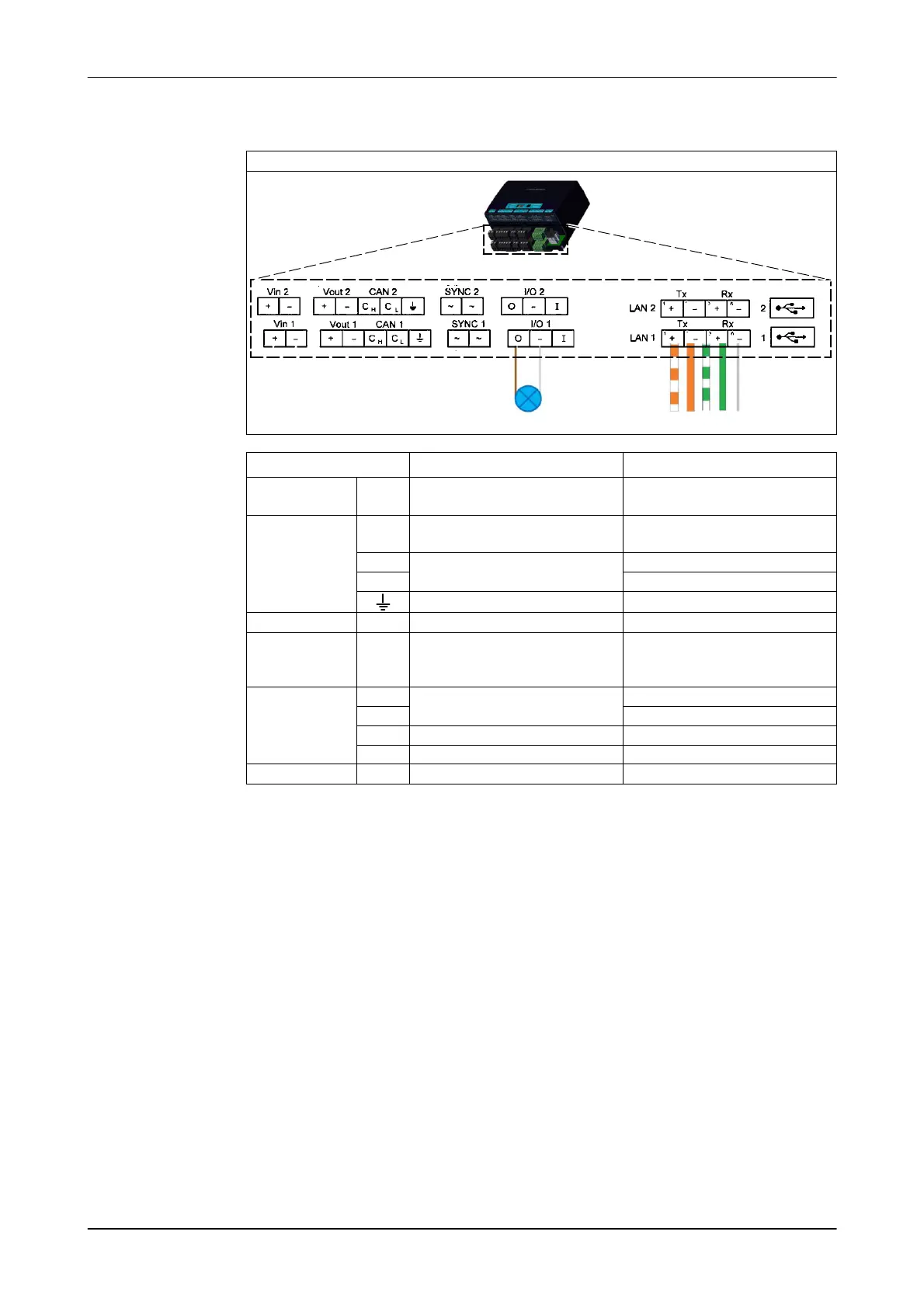
Connect control unit
1. Connect the cable to the control unit (LAN1)
Control unit connections (VP8002)
1236
Inputs / Outputs Function Cables
Vin 1/ Vin 2 +
-
Input 25 VDC Red
black
Vout1/CAN1 /
Vout2/CAN2
+
-
Output 25 VDC Red
black
(CH)
Transceiver connection
blue
(CL) Blue/white
CAN-bus cable shielding
SYNC1/SYNC2 ~ Antenna synchronisation
I/O1 / I/O2 O
-
I
Out
Negative
Digital input
I/O1 for status light display
LAN 1 / LAN 2
Tx +
Transmitting
Orange/white
Tx- orange
Rx+
Receiving
green/white
Rx -
Shielding
green
1/2 USB connection
2. Connect to the control system (LAN2)
Examples:
- CowScout (VP4102)
Alternative connection also via CAN bus
- AutoSelect-Ethernet
See the corresponding manual for more information on this subject.