913323/CP0112 24 PRINTED IN U.S.A.
NOTE: The rear wheels are not self-centering.
Make sure all wheels are in a straight-ahead posi-
tion before changing the steering mode.
Any of the steering modes can be used in forward and
reverse travel. The operator should learn to anticipate
changes in machine movement if the steering mode
must be changed.
B - Clutch Cutout: When activated, this switch allows
faster engine acceleration and more power to the
hydraulic system, without power to the drive axles,
while the service brake pedal is pressed.
In the “OFF” position, the clutch mechanism of the
transmission remains engaged when the brakes are
applied. In the “ON” position, the clutch mechanism is
disengaged when the brakes are applied.
Normal brake force will hold the machine in position
while accelerating the engine to power hydraulic con-
trol functions during load placement.
C - Parking Brake: When the machine is parked, this
switch should be pressed to actuate the parking brake
mechanism in the front axle.
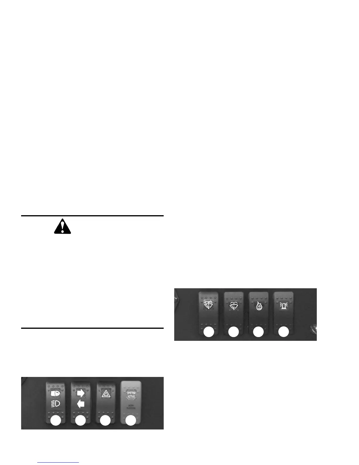
Middle Row Switches
Switches have graphic symbols to indicate function
and effect. The following descriptions start with the
first switch on the left.
NOTE: Some switches are optional and may not
be on machine.
A - Head Lights/Work Lights: Pressing the top of the
switch will illuminate the lights mounted on the top of
the operator’s station and the red tail lights, for use in
forward travel operations. Pressing the bottom of the
switch will illuminate the lights at the end of the boom
in addition to the lights on the operator’s station, for
additional lighting in working operations.
B - Turn Signal: This switch is used to indicate the
direction of a turn with the tail lights. Press the right
arrow for a right turn; press the left arrow for a left
turn. Return the switch to the center position after the
turn is completed.
C - Hazard: This switch can be activated to make the
tail lights flash on and off in case the machine is stalled
or temporarily stopped in a traffic area on the road or
jobsite.
D - Personnel Work Platform: This is a red switch
used to activate the Personnel Work Platform (PWP)
System. When activated, an amber lamp in the switch
will be on.
NOTE: This lamp will flash on and off, indicating
that the system is not yet fully functional, until the
brakes are held on for three or more seconds.
Bottom Row Switches
Switches have graphic symbols to indicate function
and effect. The following descriptions start with the
first switch on the left.
NOTE: Some switches are optional and may not
be on machine.
A1 and A2 - Wiper/Washer: The windshield and top
window of the operator’s station are each equipped
with a wiper and washer mechanism. Switch “A1”
operates the wiper and washer on the windshield;
switch “A2” operates the wiper and washer on the top
window.
WARNING
UNATTENDED MACHINE HAZARD
Activate parking brake switch and lower
attachment tool to ground before leaving
machine. An unattended machine can move or
roll and cause death or serious injury to oper-
ator or bystanders.
Periodically check the parking brake opera-
tion to maintain adequate holding power.
Always be sure the parking brake switch is off
when resuming machine operation.
A DCB
A1 BA2
C
 Loading...