V 02/18
44 • CAN bus OptiStar CG08(-C)
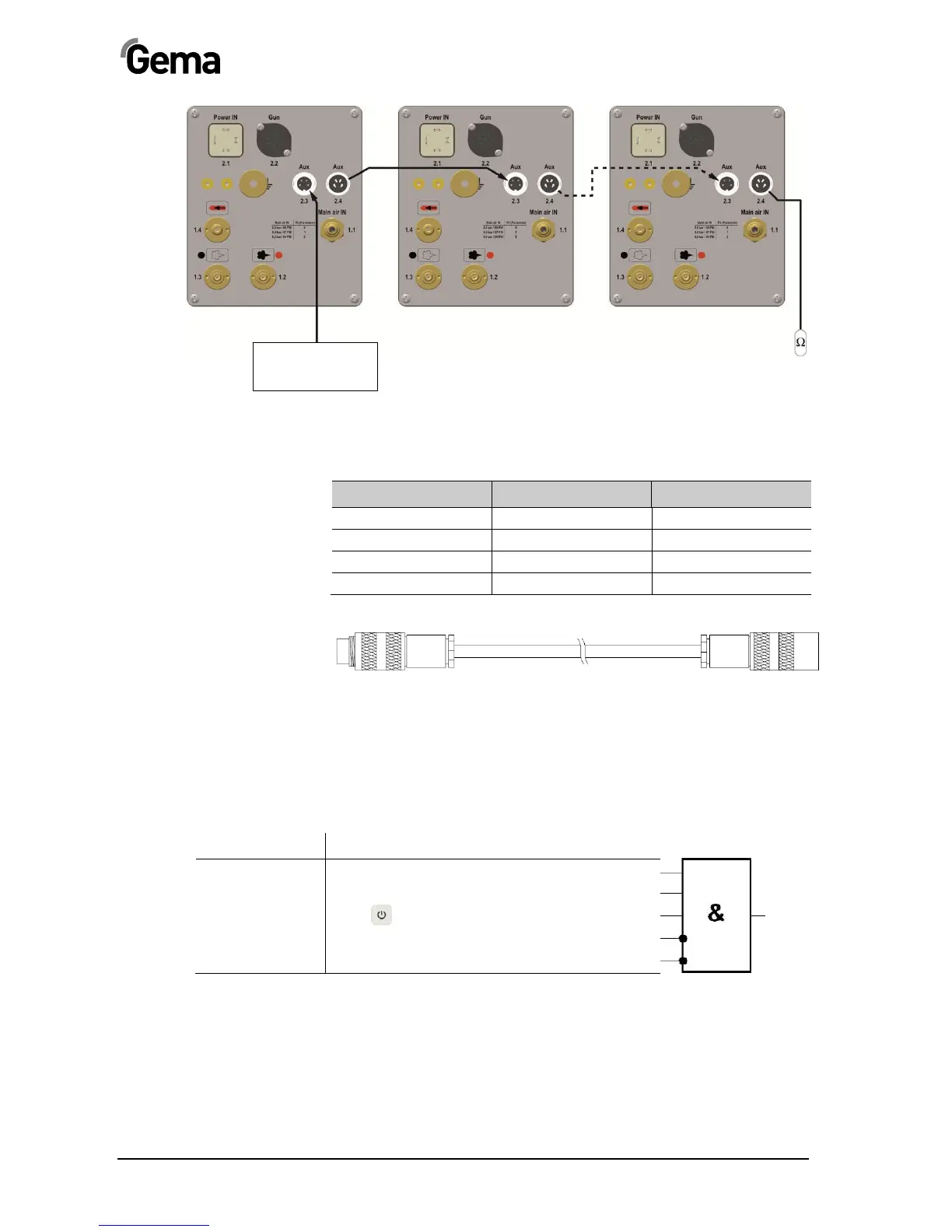
CAN bus - connections
CAN bus cable - plug assignment
Pin Signal Color
1 GND white
2 +24 VDC black
3 CAN H black
4 CAN L black
CAN bus cable
System release in network operation
The system release logic starts and stops the powder conveying and high
voltage. The release is determined due to the several internal and
external signals.
Signal Designation
Ext. Release System signal on mains plug
Trigger Gun connected
Gun release
Local
or command via Remote Interface
Error Lock Device error
System Lock Parameter input
PLC control with
CAN bus
Terminal resistor
OptiStar no. 1 OptiStar no. 2 OptiStar no. 127 (max.)
System
release
 Loading...