Do you have a question about the Gema OptiStar CG08-C and is the answer not in the manual?
Explains the meaning of safety symbols used in Gema operating instructions.
Defines the intended use of the OptiStar CG08(-C) and manufacturer liability.
Provides an overview of the manual's content and guidance for using the control unit.
Specifies the software version covered by this documentation.
Details safety aspects related to the OptiStar CG08(-C) Gun control unit's integration.
Details the intended use of the OptiStar CG08(-C) Gun control unit for powder coating.
Lists common examples of misuse for the OptiStar CG08(-C) gun control unit.
Lists available versions of the OptiStar CG08 and their CAN bus compatibility.
Specifies which gun types are compatible with the OptiStar CG08(-C).
Provides electrical specifications like input voltage, frequency, and current.
Details compressed air requirements and specifications for the control unit.
Lists the physical dimensions (width, depth, height, weight) of the unit.
Provides guide values for powder output based on various conditions.
Specifies conveying air, supplementary air, and electrode rinsing air flow rates.
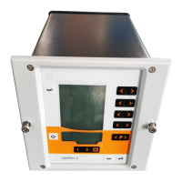
Provides a visual overview of the OptiStar CG08(-C) unit and its main parts.
Details the displays and input buttons for operating the control unit.
Describes the displays and LEDs shown on Level 2 of the unit's interface.
Lists and explains the function of each input key and switch on the unit.
Illustrates and lists connections for compressed air hoses and cables.
Details the pin assignments for power, gun, and auxiliary connections.
Lists the items included in the scope of delivery for the unit.
Explains the two operating modes: Preset and Program.
Describes the three preset application modes for coating different part types.
Details the adjustable mode with 250 definable programs.
Explains the PCC mode for precise current control in complex coating.
Describes the PowerClean mode for blowing out powder and moisture.
Details the functionality to monitor the service life of up to four wearing parts.
Explains the trigger counter for total time in days of trigger time.
Explains the keyboard lock feature to prevent modification of parameter values.
Describes the 8 brightness settings for the display and auto power save mode.
Explains how to zero out powder output for compensation to different hose lengths.
Lists basic conditions required before starting up the gun control unit.
Describes how to mount the OptiStar CG08(-C) gun control unit.
Provides step-by-step instructions for connecting the unit and its components.
Explains the use of system parameters for configuring the control unit.
Guides the user on how to enter and adjust system parameters.
Details the configuration of system parameter P00 for device type.
Explains the use of system parameter P03 for determining air measurement units.
Describes system parameter P10 for controlling the level of detail in log reports.
Guides on selecting predefined operating modes and their preset values.
Explains how to start and use the adjustable program mode.
Details how to set powder output and total air volume for coating.
Explains how to adjust the electrode rinsing air based on nozzle type.
Explains how to adapt the control unit with correction values.
Guides the user on entering and adjusting correction values.
Details procedures for correcting powder output and powder hose settings.
Step-by-step guide for correcting powder output.
Step-by-step guide for correcting powder hose settings.
Illustrates the influence of powder hose correction on powder output.
Explains the use of the daily correction value C2 for powder volumes.
Details the two-step process for activating the cleaning mode.
Explains the trigger counter for total time in days of trigger time.
Shows how to view the remaining service life of wearing parts.
Explains how to deactivate the monitoring of wearing parts.
Describes how to adjust the display brightness and auto power save.
Guides on activating and deactivating the keyboard lock feature.
Explains how to check the software version of the control unit.
Details the procedure for resetting the unit's RAM to factory settings.
Provides instructions for shutting down the unit for extended periods.
Describes the hardware setup for connecting OptiStar units via CAN bus.
Details the pin assignments and colors for the CAN bus cable.
Explains the system release logic in a network operation.
Explains how to set the baud rate using system parameter P05.
Explains how to set the Node ID using system parameter P06.
Explains how the software monitors functions and indicates faults with help codes.
Describes how error diagnosis codes (help codes) are displayed and acknowledged.
Provides a comprehensive list of error codes and their remedies.
Describes how errors are displayed and how to handle them.
Guides on how to order spare parts, including required specifications.
Lists complete gun control units and covers as spare parts.
Lists spare parts for the front plate and power pack assembly.
Lists spare parts for the inside rear wall of the unit.
Lists spare parts for connections, hoses, and cables.
| Model | OptiStar CG08-C |
|---|---|
| Type | Control Unit |
| Power Supply | 100-240 V AC |
| Input Voltage | 100-240 V AC |
| Frequency | 50/60 Hz |
| Rated Output Voltage | 24 VDC |
| Protection Category | IP54 |
| Max. Water Vapor Content of Compressed Air | 1.3 g/m³ |
| Max. Oil Vapor Content of Compressed Air | 0.1 mg/m³ |
| Number of Outputs | 1 |
| Operating Temperature Range | 0°C to 40°C |
| Max. Input Pressure | 10 bar |
| Min. Input Pressure | 6 bar |
| Protection Class | Class I |
| Ambient Temperature | 0°C - +40°C (32°F - +104°F) |