B
Brandi JacksonAug 17, 2025
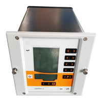
What to do if Gema Control Unit H09 error appears?
- VvfrancisAug 17, 2025
If the Gema Control Unit displays the H09 error, it means the powder output multiplied by the powder hose length factor and the daily correction value exceeds 100%, or the daily correction value is too large. To resolve this, reduce the powder output and/or reduce the daily correction value.