C
christianallenSep 13, 2025
What does error H01 mean for Gema Control Unit?
- BBrooke MendezSep 13, 2025
The FlowControl module is defective, check system parameter P0 and set it to basis equipment without FlowControl (P0=0).
What does error H01 mean for Gema Control Unit?
The FlowControl module is defective, check system parameter P0 and set it to basis equipment without FlowControl (P0=0).
Explains the meaning of DANGER, ATTENTION, and NOTE symbols used in the manual.
Details the intended use of the OptiStar CG06 and manufacturer's responsibility.
General safety information regarding powder spraying equipment and potential hazards.
Emphasizes operator responsibility for safe operation and awareness of hazards.
Outlines specific safety duties for the operating firm and personnel.
Discusses hazards related to power, powder, static charges, and grounding.
Lists essential safety measures for electrostatic powder coating operations.
Lists relevant German professional association guidelines and regulations.
Lists relevant European standards for electrostatic coating and machine safety.
Lists relevant VDE regulations for high voltage equipment and electrostatic spraying.
Lists specific security measures for installation and start-up.
Introduces the manual's purpose and scope for the OptiStar CG06.
Specifies the software version covered by the document.
Defines the intended use of the OptiStar CG06 for Gema powder coating guns.
Lists key features and capabilities of the OptiStar CG06 Automatic gun control unit.
Describes core functionalities like intuitive operation and program saving.
Details advanced features such as spray current regulation and bus connections.
Summarizes setting possibilities, correction values, request values, features, and options.
Explains the two operating modes: Preset and Program.
Describes the three predefined application modes available.
Details the 250 user-programmable settings.
Lists available versions of the OptiStar CG06 and their features.
Lists compatible Gema powder guns for the OptiStar CG06 control unit.
Provides specifications for voltage, frequency, power, protection type, and approvals.
Details compressed air connection, input pressures, and air quality requirements.
Lists the physical dimensions and weight of the OptiStar CG06 unit.
Provides detailed air flow rate data for various configurations and air types.
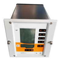
Describes the function of each display segment (A1-A5) and LED indicator.
Explains the function of each input key (T1-T16, S1/S2) and the SELECT key.
Provides information on displaying programs, actual values, and preset values.
Illustrates and lists all connection points on the rear of the OptiStar CG06 unit.
Details pin allocation for CG06, CG06-C(F), and CG06-D(F) for Aux connections.
Provides step-by-step instructions for connecting the OptiStar CG06 unit and components.
Details pin assignments for Power IN, Gun, and Aux for CG06 models.
Details pin assignments for the CAN IN socket (2.4 Aux).
Details pin assignments for the DigitalBus plug (2.4 Aux).
Covers setting the device type and preparing the powder hopper/container.
Outlines steps for daily start-up and selecting operating modes.
Explains how to select and use predefined application modes.
Describes the suitability of the flat parts mode.
Describes the suitability of the complicated parts mode.
Describes the suitability of the recoating mode.
Details how to adjust powder output and total air volume.
Explains the conditions required for the gun to spray powder.
Provides instructions for setting the electrode rinsing air volume.
Provides instructions for setting the shaping air volume.
Instructions for the actual powder coating process.
Explains how to remotely control functions using the OptiSelect GM02 gun.
Details the procedure for shutting down the OptiStar CG06 unit.
Notes that programs and preset modes are saved automatically.
Illustrates the relationship between high voltage and spray current in Preset mode.
Illustrates the relationship between high voltage and spray current in Program mode.
Explains the configuration of system parameters saved in memory.
Guides the user on how to access and modify system parameters.
How to view trigger hours and software version.
Explains the keyboard lock function and what it affects.
Details configuration and operation with the Tribo gun.
Explains how to adjust powder output and hose correction values.
Step-by-step guide for performing powder output correction.
Detailed procedure for powder output correction with example table.
Procedure for powder hose correction and calculating the correction factor.
Illustrates the influence of powder hose correction on powder output.
Explains how to reset the unit to factory settings.
Describes the two-step process to activate the cleaning mode.
Details the features and benefits of the FlowControl module.
Explains the DigitalBus module for decentralized automation and PLC connection.
Illustrates how OptiStar units are controlled by a master unit via DigitalBus.
Describes the structure of the parallel bus interface for data and control signals.
Lists commands, their value ranges, and units for DigitalBus communication.
Illustrates the timing sequence for DigitalBus communication.
Details timing parameters like setup time, hold time, and pulse length for DigitalBus.
Provides a pin and bit allocation table for the DigitalBus connector.
Shows plug assignments for connecting the OptiStar to a PLC via Digital Connector CD02.
Introduces the CAN bus interface and its operation as a CANopen Slave.
Describes how OptiStar control units connect to a PLC via CAN bus cables.
Details the pinout and color coding for CAN bus cables.
Explains system release conditions for network operation via CAN bus.
Guides on setting Node-ID and Baud rate using system parameters P5 and P6.
Visual representation of the pneumatic system of the OptiStar CG06.
Part 1 of the electrical diagram showing display and mainboard connections.
Part 2 of the electrical diagram showing mainboard module connections.
Instructions for repairing electrical components like fuses and power supply boards.
Step-by-step guide to replacing fuses in the control unit.
Step-by-step guide to replacing the power supply board.
Instructions for replacing the front plate of the control unit.
Instructions for repairing pneumatic components.
How to safely disconnect pneumatic hoses.
How to reconnect pneumatic hoses.
General information on software error messages and monitored systems.
Explains error code format (Hnn) and lists Pneumatics codes.
Lists error codes for High voltage, Power supply, EEPROM, and Parallel interface.
Lists error codes for CAN bus, value ranges, and throttle motors.
Notes on how errors might appear and how to handle temporary errors.
Provides instructions and examples for ordering spare parts.
Lists general spare parts for the basic OptiStar CG06 unit and its variants.
Lists spare parts for the inside rear wall of the CG06 unit.
Lists spare parts for the outside rear wall of the CG06 unit.
Lists spare parts for the inside rear wall of the CG06-C unit.
Lists spare parts for the outside rear wall of the CG06-C unit.
Lists spare parts for the inside rear wall of the CG06-CF unit.
Lists spare parts for the outside rear wall of the CG06-CF unit.
Lists spare parts for the inside rear wall of the CG06-D unit.
Lists spare parts for the outside rear wall of the CG06-D unit.
Lists spare parts for the inside rear wall of the CG06-DF unit.
Lists spare parts for the outside rear wall of the CG06-DF unit.
Lists spare parts for the enclosure and power pack of the CG06 unit.
Lists spare parts for the front plate of the CG06 unit.
| Brand | Gema |
|---|---|
| Model | OptiStar CG06 |
| Category | Control Unit |
| Language | English |