V 09/18
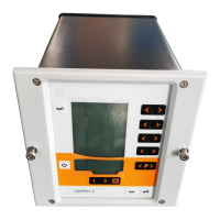
OptiStar CG06 Automatic gun control unit Options • 47
The interface consists of 15 digital inputs and 1 digital output. The digital
inputs are split to a data bus, consisting of 12 bits and a control bus, con-
sisting of 3 bits. The digital output is an error message bit for composite
error messages of the equipment.
Structure of the 16 bit parallel bus
D8 D7 D6 D5D4D3D2D1D0A2A1A0Remote System Strobe Error
Value Command Input Output
Data Control Status
Data bits (Data)
The data bus width is 12 bits. The first 9 bits are used to transfer the data
for the different operating parameters (preset values) to the control unit.
The data for the corresponding preset values (powder output, total air,
electrode rinsing air, shaping air, high voltage limitation value, current
limitation value, program number) are assigned with an identification
number, consisting of 3 bits.
Control bits (Control)
For inputs, there are 3 control bits available:
- Strobe - Activate data transfer
- System - System release OptiStar
- Remote - Operating mode
Status bits (Status)
For output, there is 1 status bit available:
- Error - Digital output composite error message, indicates all
errors which are present in the control unit (error list, can be
deleted locally). Error polarity = acc. to System parameter P8