Do you have a question about the Gema OptiMove CR07 and is the answer not in the manual?
Explains standard safety warning symbols used in the manual.
Defines the intended use of the OptiMove CR07 and non-compliant applications.
Details safety precautions specific to the OptiMove CR07's technical specifications.
Outlines critical safety measures and warnings for operation and maintenance.
Introduces the manual's purpose and scope, guiding users on its content.
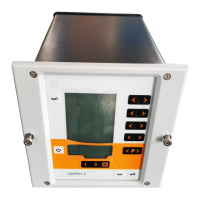
Describes the core functions and purpose of the OptiMove CR07 Axis control unit.
Provides detailed technical specifications, including electrical and dimensional data.
Explains the physical structure and enclosure of the OptiMove CR07 unit.
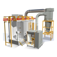
Details how the OptiMove CR07 unit operates within the system.
Illustrates the functional configuration and component connections of the unit.
Describes the control panel's display modules (A1-A3) and input keys (T7-T9, sel).
Explains Manual, Remote, Semiautomatic, and Keyboard lock modes for unit operation.
Details the rear panel connectors for power, signals, and communication interfaces.
Guides through the essential steps for bringing the unit into operation safely.
Explains how to adapt the unit's behavior using system parameters.
Covers general operation, including program recall and management.
Instructs on the procedure for powering the axis control unit on and off.
Explains the process of referencing the axis for accurate positioning.
Details how to initiate and halt axis movement using the control panel.
Describes methods for selecting and activating different operational programs.
Explains how to view the duration of a program cycle.
Guides on modifying existing program parameters and data.
Introduces the concept of operating modes and their selection via parameter P2.
Describes continuous stroke movement operation with keyboard control.
Details how to edit and set program values like reversing points and speeds.
Explains the creation and execution of multi-step programs.
Covers pendulum operation controllable via external signals.
Describes a specific sequence program for gun cleaning operations.
Guides on using the keyboard for 'Teach-In' setup in specific operating modes.
Details keyboard-based setup for sequence programs.
Explains the procedure to reset the unit to factory default settings.
Lists the default parameter values loaded after a RAM reset.
Introduces the DigitalBus interface for connecting to superordinated control units.
Details the data, control, and status bits within the parallel bus interface.
Explains the software logic and signal handling for OptiMove units.
Illustrates control sequences for program number changes and parameter settings.
Describes the process of data transfer initiated by the Strobe control signal.
Provides pin assignments for the Digital Connector CD02 interface.
Explains the CAN bus interface for network operation as a CANopen slave.
Describes the physical connection of OptiMove units via 4-pin CAN bus cables.
Details the pinout and color coding for CAN bus cables.
Guides on assigning a unique Node-ID for network identification.
Explains how to configure the communication speed for the CAN bus.
Introduces error message display and the process for error elimination.
Lists axis-related error codes (H01-H12) and their corresponding actions.
Lists hardware-related error codes (H20-H23) and required actions.
Lists DigitalBus interface error codes (H30-H32) and their remedies.
Lists CAN bus error codes (H40-H46) and their respective fault resolutions.
Overview of all connector pin assignments for the unit.
Details pin functions for the Power IN connector (2.1).
Details pin functions for the Drive Supply connector (2.2).
Details pin functions for the Drive I/O connector (2.3).
Details pin functions for the Aux DigitalBus parallel interface (2.4).
Details pin functions for the CAN bus input connector (2.5).
Details pin functions for the CAN bus output connector (2.6).
Instructions and specifications for ordering replacement parts.
Lists spare parts for the front plate and power pack assembly.
Lists spare parts for the rear panel components.
Provides a table for recording program settings and parameters.
| Brand | Gema |
|---|---|
| Model | OptiMove CR07 |
| Category | Control Unit |
| Language | English |