V 12/13
OptiMove CR07 CAN bus • 49
CAN bus
General information
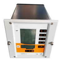
The OptiMove CR07 Axis control unit is fitted with a CAN bus interface as
standard, and can be operated as a simple CANopen slave in a network
with a central control unit (Master).
The communication between the users in the network takes place by
CAN bus, therefore each existent component must be classified with an
individual user address (Node-ID = identification number). The allocation
is described in the section "Setting the user address (ID number)". The
transmission speed setting is determined by adjusting the Baud rate (see
therefore "Setting the Baud rate").
Hardware
The OptiMove control units are connected to the central PLC control unit
with 4 pin CAN bus cables. The last bus client is fitted with a terminal
plug with terminal resistor in order to terminate the network correctly. A
maximum of up to 125 users can be connected in a network.
CAN bus cable - plug assignment
Pin Signal Color
1 GND white
2 +24 VDC black
3 CAN H black
4 CAN L black
CAN bus cable
 Loading...