V 09/18
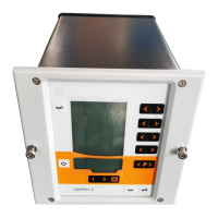
28 • Start-up and operation OptiStar CG06 Automatic gun control unit
2.3 and 2.4 Aux connections
Equipment Allocation 2.3 Allocation 2.4
CG06 closed closed
CG06-C(F) CAN bus (OUT) CAN bus (IN)
CG06-D(F) closed DigitalBus
Connection guide
1. Connect the compressed air supply from the compressed air
circuit to the 1.1 Air supply IN (1/4" male quick release)
connection on the control unit
NOTE:
The compressed air must be free from oil and water!
2. Connect the grounding cable to the control unit with the
grounding screw, and the 5 m long grounding cable with the
clamping clip to the booth or the conveyor. Check ground
connections with Ohm meter and ensure 1 MOhm or less
3. Connect the gun cable plug to the socket 2.2 on the rear side
of the control unit
4. Connect the rinsing air hose to the electrode rinsing air out-
put 1.4 and to the powder gun
5. Insert the injector, connect the powder hose to the injector
and to the powder gun
6. Connect the red hose for the conveying air to the correspond-
ing output 1.2 on the rear of the control unit and to the injector
7. Connect the black hose for supplementary air to the corre-
sponding output 1.3 on the rear side of the control unit and to
the injector (this hose is electrically conductive)
8. Connect the hose for shaping air (optional) to the corre-
sponding output 1.5 on the rear side of the control unit
9. Connect the mains cable to the 2.1 Power IN plug and screw it on
Connecting guide - overview
Injector
Powder gun
Shaping air (optional)
Pressure regulato
after filter
(5.5/6.0/6.5 bar)