10 Generac
®
Power Systems, Inc.
Section 1 — General Information
E Option Control Panels
Remote Annunciator Panel
(Refer to manuals 0A7450 and 0A9825)
The serial connections can be configured to allow the
control panel to connect to a remote
annunciator/remote relay panel, which is configured
as RS485, to meet NFPA 110. Only one communica-
tion port is available for either a modem or remote
annunciator.
NOTE:
The following diagram and instructions apply only
to those units manufactured before January 2000.
Units manufactured after January 2000 incorpo-
rate a selector switch on the back of the control
module. This switch will allow selection of either
RS232 or RS485 without opening the module.
Altering the Serial Communications Setup
The E option control panel is capable of being used
with either a modem or a remote annunciator/
remote relay panel, depending on the configuration of
the serial connections. The unit comes set up for con-
nection to a modem (RS232). In order to use the con-
trol panel with a remote annunciator/remote relay
panel (RS485), adhere to Figure 1.5 and the instruc-
tions that follow.
1. Remove harness retaining screws, then unplug all
five wire harnesses from the back of the E panel
control module.
2. Remove the four phillips head screws retaining the
rear cover of the control module.
3. Open the back of the control module.
4. Locate the DB-9 wire harness that runs from the
DB-9 connector on the back panel to the black
header on the lower circuit board inside the con-
trol module.
5. Carefully remove the black connector from
the header by pressing the locking tab and
lifting up.
6. Insert the black connector into the RS485
header (J11). Make sure that the connector is fully
inserted and that the locking tab snaps into place.
7. Replace the back panel and the four screws.
Figure 1.5 – E Panel Serial Communications
Setup Modification
USER PASSWORD
The user can set the password. This is a six-digit
number and is initially set to 000000.
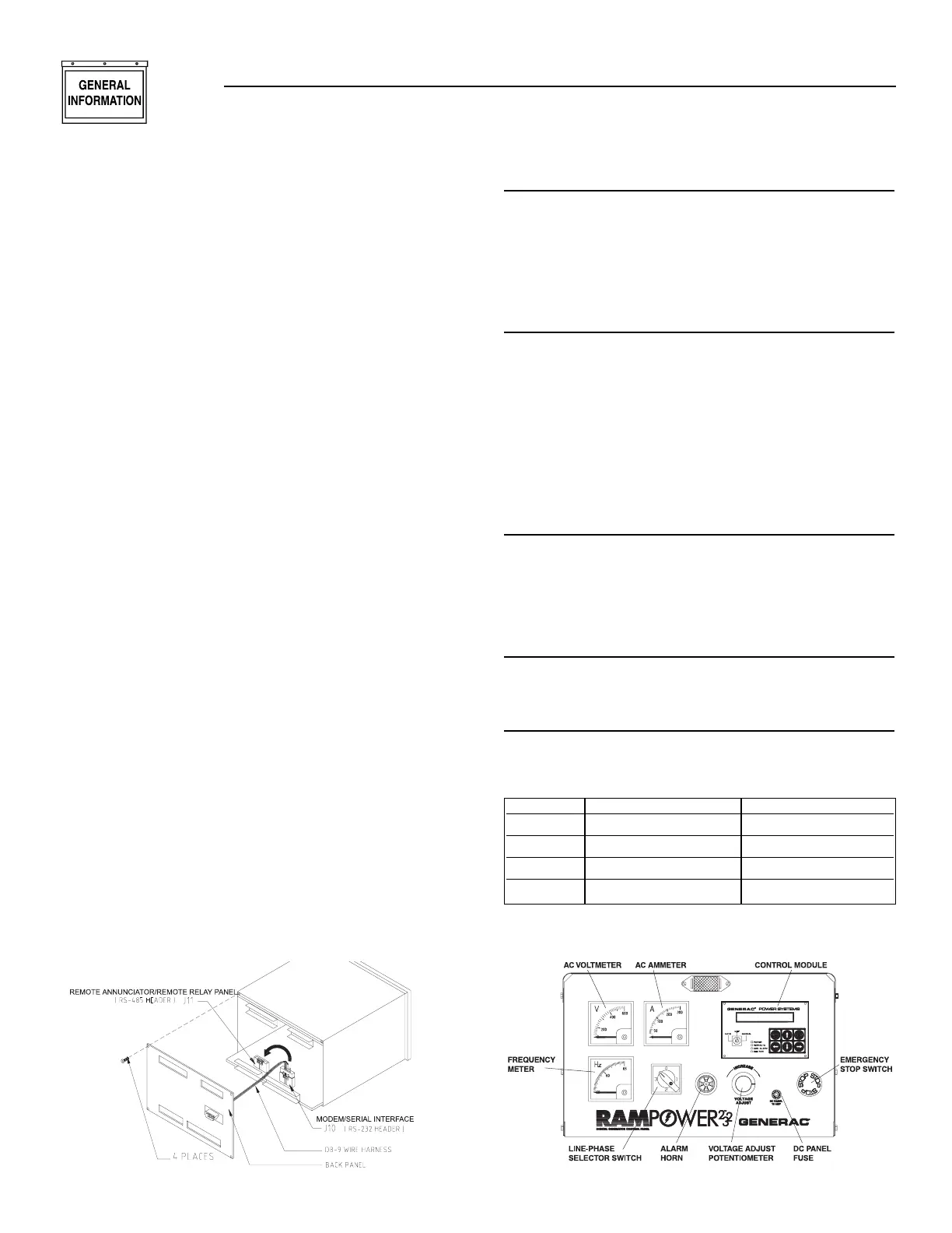
ADDITIONAL PANEL COMPONENTS
In addition to the control module, the E option panel
contains the following components (see Figure 1.6):
AC VOLTMETER
This meter indicates the generator AC output voltage.
To determine the nominal rated AC voltage of the
unit, refer to the unit’s data plate.
NOTE:
Some generators are re-connectable to a variety of
voltages. Some units may be equipped with a
rotary “Voltage Selector Switch.” Be sure to read
the “Generator AC Lead Connections” section in
the Owner’s Manual.
AC AMMETER
This meter indicates the current draw of connected
electrical loads, in amps. Also see “Line-phase
Selector Switch.” For continuous operation, never
exceed the rated maximum continuous current
capacity of the generator.
FREQUENCY METER
This meter indicates the generator’s AC output fre-
quency in “Hertz” (cycles per second).
LINE-PHASE SELECTOR SWITCH
This four-position switch permits selection of either
line-to-line or line-to-neutral readings on the panel volt-
meter and ammeter. Switch positions are as follows:
Figure 1.6 – E Option Panel Components
Switch Single-phase Units Three-phase units
1 Line E1 to Neutral Line E1 to E2
2 Line E3 to Neutral Line E2 to E3
3 Line E1 to E3 Line E3 to E1
OFF No Reading No Reading