Generac
®
Power Systems, Inc. 3
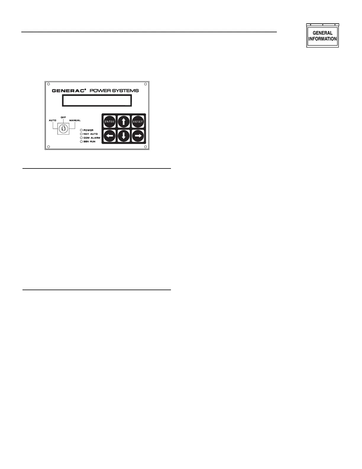
Figure 1.1 – Control Module Layout
KEYPAD
The keypad consists of six keys labeled as follows:
↑ (up)
,
↓ (down)
,
← (left)
,
→ (right)
,
Enter, and Reset.
The left and right arrow keys are used to select the dif-
ferent pages on the display. The up and down arrow
keys are used to scroll between options within a page.
They also are used for selecting characters when the
user is entering messages or parameters for the
alarms. The left and right arrow keys move the cursor
when the user is entering data. The enter key takes the
user into a page on the display to change data (when
applicable) and also accepts data that has been entered.
It also is used to accept an alarm. The reset key ignores
data that has been entered and returns the original
value. It also is used to return from the parameter entry
mode once the user has finished changing the data, and
to reset any latched alarms that have cleared.
DISPLAY
The display is organized into a series of pages, each
page displays information about the status of the gen-
erator. For example, the “Alarm Status Message Page”
displays the highest priority current alarm or status
condition. The user will be able to scroll between the
pages using the left and right arrow keys. Certain
actions also cause the display to change pages, e.g.,
when an alarm becomes active, the display automat-
ically will go to the alarm status page and display the
alarm message.
The back light for the display is normally off. If the
user presses any key, the back light will come on
automatically and remain on for five minutes after
the last key was pressed. It also will come on if any
status message is current, which means the display
will switch to the alarm status page. The back light
will flash when an alarm or shutdown message is
active, and the audible alarm will sound.
When the display is showing certain pages, the user
is able to scroll between relevant items within the
page using the up and down arrow keys. For example,
if the display is showing the “Alarm Log Page,” the
user can use the up and down arrow keys to scroll
between the entries on the alarm log. A description of
each page is given below.
Software Version Page
This page displays the software revision. Pressing the
enter key in this page will perform a display and LED
test.
Generator Command Page
This page displays the command sent to the genera-
tor. The possible commands are as follows:
• Generator switched off
• Generator in manual mode
• Generator in auto mode – stop command
• Generator in auto mode – remote run command
• Generator in auto mode – serial link run
command
Generator Status Page
This page displays the current status of the generator.
Options will be as follows:
• Stopped – ready to run
• Stopped – start inhibit active
• Pre-heating (with timer counting down)
• Attempting to start (with timer counting down and
number of attempts)
• Pausing before start attempt (with timer counting
down and number of attempts)
• Started – running up to speed
• Warming up
• Ready to accept load
• All alarms enabled
• Cooling down
• Stopping
• Stopped due to alarm
If the user has not pressed a key for some time, any
change in status will cause this page to be displayed
provided that there are no active alarms or status
messages from other inputs. If an alarm condition
occurs, the alarm status page will be displayed auto-
matically.
Alarm Status Message Page
This page displays alarm messages and program-
mable status messages. Messages are displayed
according to priority, with the shutdown alarms
having highest priority, and status messages having
lowest priority.
Section 1 — General Information
E Option Control Panels