Generac
®
Power Systems, Inc. 23
TROUBLESHOOTING
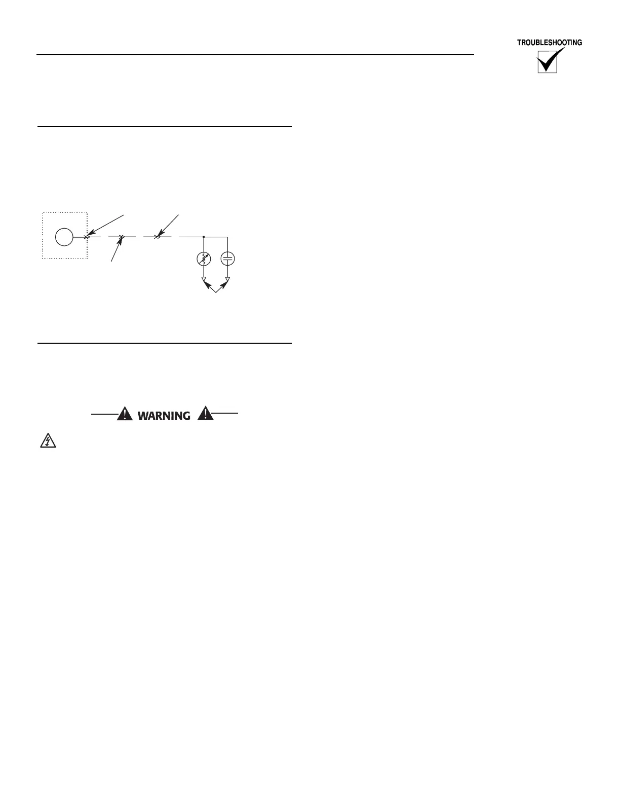
Figure 3.2 — Water Level Sensor Connections
TESTING THE CONTROL PANEL
It is relatively easy to do a thorough test of the E
Panel's Low Coolant Level input.
In most cases it is necessary to run the engine while
doing this testing.
Once the engine has started, there will be high
voltage inside the generator's control panel
and at CON4 of the E Panel.
Open circuit testing
This test checks the high end of the low coolant level
input.
1. With the generator stopped, remove the 85 wire
from the control panel terminal strip. This simu-
lates a sender open circuit condition.
2. Start the Generator.
2.1 The generator should not shut down on Low
Coolant Level with the 85 wire disconnected.
If the generator does shutdown on low
coolant level, there is a fault with the E Panel.
2.2 With the 85 wire still disconnected, use a DC
volt meter to measure the voltage between the
85 wire (the end still connected to the E
Panel) and ground. This voltage should be 10
volts DC or greater.
If this voltage is below 10 volts DC, there is a
fault with the E Panel. Replace the E Panel.
2.3 Stop the generator.
Short circuit testing
This test checks the low end of the low coolant level
input.
1. Reconnect the 85 wire to the control panel termi-
nal strip. Connect a jumper wire between the 85
and 0 locations on the control panel terminal
strip. This simulates the HWT switch closing to
ground.
2. The E panel should respond as follows:
2.1 E Panels with V1.03 and earlier software:
The E Panel will sound the alarm and display
a low coolant level fault.
2.2 E Panels with V1.04 and later software: Start
the generator and observe the following:
2.2.1 The E Panel should start normally.
2.2.2 Once the engine has started, the hold
off timer will start.
2.2.3 Once the hold off timer expires, the E
Panel will shut the engine down and
display a low coolant alarm.
Control panel testing complete
1. Shut down the generator engine.
2. Remove the jumper between the 85 and 0 loca-
tions.
Test Results
1. Tests 1 and 2 Pass:
Move on to the next test "Checking the wiring
between the E Panel and the LCL/HWT".
2. If either test 1 or 2 failed:
2.1 Repeat the open and short circuit testing
directly at the back of the E Panel as follows:
Open: The 85 wire should be removed from
CON2-7.
Short: With the 85 wire still removed, insert
a jumper wire into CON2-7. Connect
the other end of the jumper to ground
(0).
After testing, remove the jumper wire from
CON2-7 and insert the 85 wire back into
CON2-7.
2.2 Test results:
2.2.1 If these tests fail again directly at the
back of the E Panel, then the E Panel
has failed and needs to be replaced.
2.2.2 If these tests pass at the back of the E
Panel, but failed at the terminal strip,
then there is a wiring error between the
E Panel and the terminal strip. Check
this wiring carefully.