Generac
®
Power Systems, Inc. 25
2. Check the devices while the generator is running.
If the E Panel is still shutting down on low coolant
level, and both devices check good in the power
down state, the devices can be checked while the
engine is running. The following tests will isolate
the two different senders and determine which
sender is causing the shutdown.
NOTE:
It is very important that the wiring between the E
Panel and the LCL/HWT was carefully checked as
described above. Incorrect wiring or damage to
any of the wiring can result in false test results.
2.1 Test the HWT switch.
2.1.1 Disconnect the 85 wire connected to
the LCL. Position the wire such that the
lug will not come into contact with any
metal surface.
2.2.2 Start and run the generator. If the gen-
erator shuts down with a low coolant
level alarm, the HWT switch is the
cause. Replace the HWT switch.
If the generator does not shut down on
alarm, stop the generator and proceed
to the next test.
2.2 Test the LCL sender.
2.2.1 Reconnect the 85 wire to the LCL.
2.2.2 Disconnect the 85 wire connected to
the HWT switch. Position the wire such
that the lug will not come into contact
with any metal surface.
2.2.3 Start and run the generator. If the gen-
erator shuts down with a low coolant
level alarm, the LCL is the cause.
Replace the LCL.
If the generator does not shut down on
alarm, stop the generator manually.
2.2.4 Reconnect the 85 wire to the HWT.
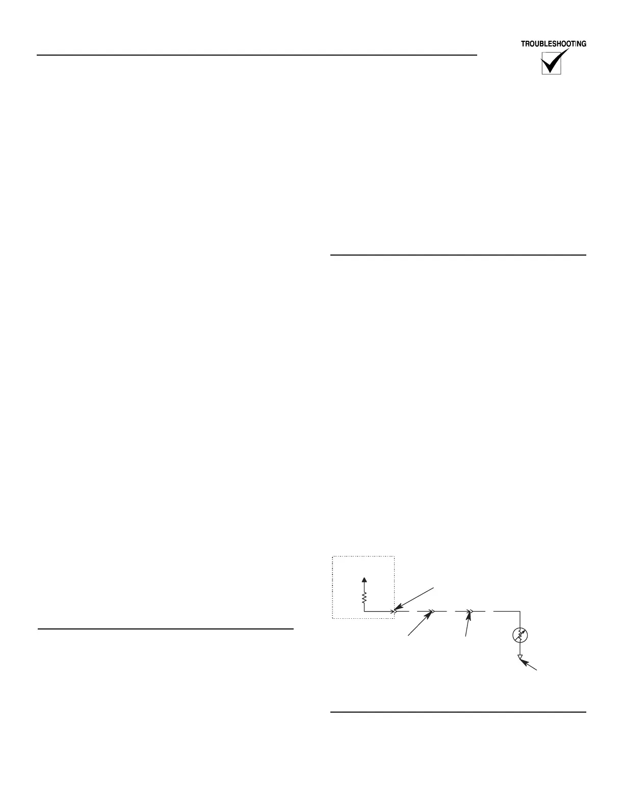
COOLANT TEMPERATURE SENSING
(Refer to Figure 3.3)
OVERVIEW
An analog Water Temperature Sender (WTS) is locat-
ed in the engine's cooling system. This sender is con-
nected to the E Panel and allows the E Panel to mon-
itor and display the temperature of the Coolant sys-
tem. Wire number 68 is used to connect the WTS to
the E Panel. The ground for the WTS is made through
the radiator frame or engine block (depending on
where the WTS is located).
Refer to the owners manual for the WTS part number
and mounting location.
The WTS is a resistive device whose resistance
changes based on coolant temperature. The resist-
ance of the sender results in a voltage being devel-
oped across the sender. As the Coolant temperature
increases, the resistance will decrease, causing the
voltage to decrease. This changing voltage is read by
the E Panel and converted into coolant temperature.
The E Panel will monitor and display the coolant
temperature anytime the DC input to the E Panel is
present.
TROUBLESHOOTING
Prior to any troubleshooting, the Coolant
Temperature parameters programmed into the E
Panel should be checked and verified. The coolant
temperature has three different set points associated
with it. They are:
• Low Coolant Temp Warning: This is a warning set
point. The generator's alarm will sound, but the
unit will continue to run.
• Pre-High Coolant Temp Warning: This is a warn-
ing set point. The generator's alarm will sound, but
the unit will continue to run.
• High Coolant Temp Alarm: This is the alarm set
point. The generator will shut down and sound the
alarm.
It is important to verify that these parameters are set
correctly for the specific unit. Check the E Panel set-
tings against the generator setup sheet. If the genera-
tor setup sheet is not available, contact Generac's
service department for the recommended settings.
Figure 3.3 — Water Temperature Sender
Connections
TESTING THE CONTROL PANEL
It is relatively easy to do a thorough test of the E
Panel's Coolant Temperature input.
Place the Auto/Off/Manual switch to the Off position
during this testing.