Generac
®
Power Systems, Inc. 35
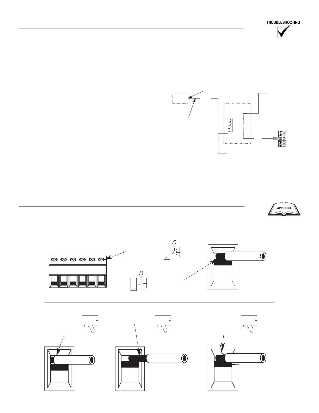
Figure 3.9 is a typical wiring schematic using a sec-
ondary relay for the E Panel fuel output. Refer to the
unit’s wiring schematics and diagrams to determine
if a secondary relay is used and for specific connec-
tions.
When the E Panel supplies + battery voltage (12 or
24VDC) from CON3-1 through wire 14A/219A, the
secondary relay is energized. The relay’s normally
open contacts will close, delivering + battery voltage
to the 14/219 location on the control panel terminal
strip.
Figure 3.9 — Typical Wiring Schematic Using a
Secondary Fuel Relay