Generac
®
Power Systems, Inc. 31
2.1.3 Shield/Drain wire. The shield is an alu-
minum foil shield that surrounds the
two conductors and runs the entire
length of the cable. The foil shield will
be cut even with the cable jacket.
The drain wire is a non insulated wire
that is in physical contact with the
shield and also runs the entire length of
the cable. The drain wire is used to
make the shield connections.
The drain wire MUST be connected to
system ground to shield the sensitive
RPM sensor signal from noise. This
ground connection is typically made at
the control panel main terminal strip.
Refer to Figure 3.6.
2.2 Check the cable at the RPM sensor. Look for
breaks, signs of over stress, excessive ten-
sion, etc.
2.3 Check all of the connection points along the
entire cable run (refer to the unit's wiring dia-
grams.) At each connection point, check for
proper wire stripping, lugging, etc.
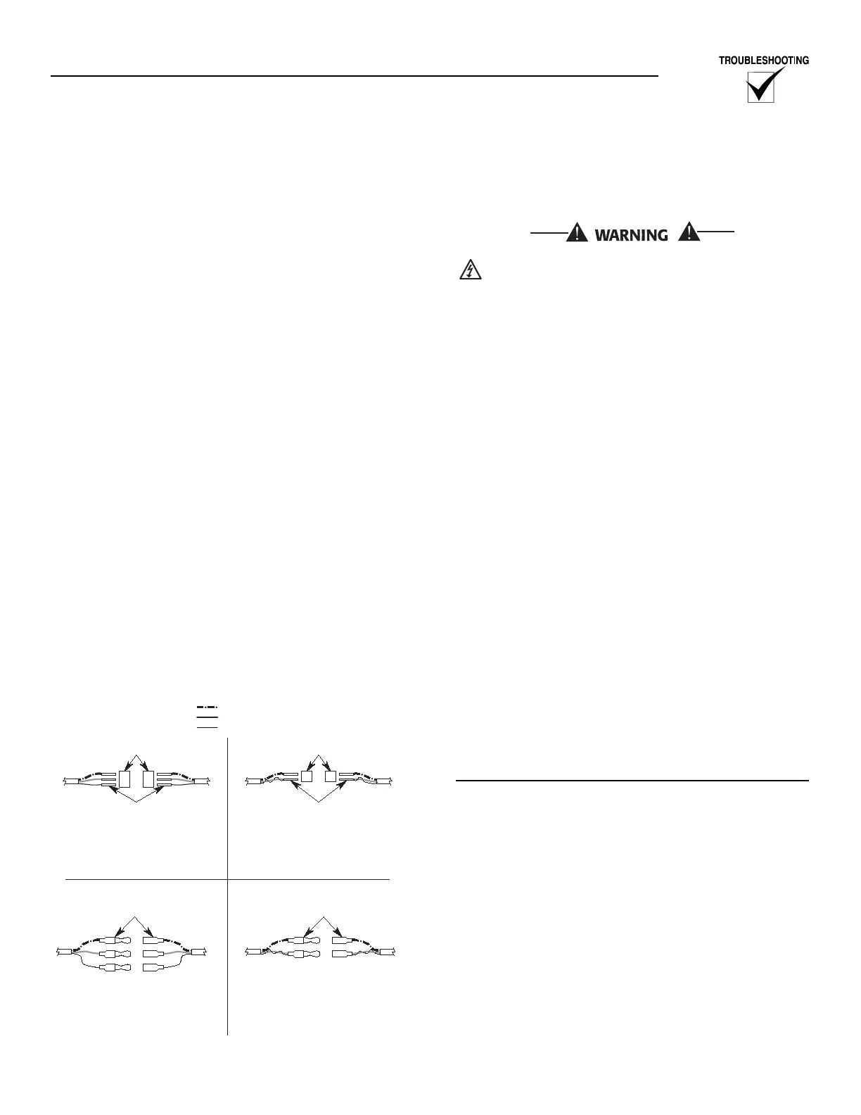
2.4 Drain wire connections. Carefully check the
drain wire connections at each connection
point. Figure 3.7 shows the different methods
that may be used for connecting the drain
wire. Note that the drain can be connected to
the 0 wire at a connection point, or it can be
run separately.
Figure 3.7 — RPM Sensor Engine Connections
3. RPM sensor voltage measurement. The RPM sen-
sor voltage can be measured at the control panel's
main terminal strip. This voltage should be meas-
ured during crank and run.
Once the engine has started, there will be high
voltage inside the generators control panel.
3.1 Using an AC volt meter, measure the voltage
at terminal positions 79 and 0.
This voltage should measure as follows:
During crank: 150 milli volts or greater
(0.150V)
During run: 500 milli volts or greater
(0.500V)
3.2 If the voltages measured are lower than what
is listed above do the following:
3.2.1 Reset the RPM sensor. Refer to Figure
3.5 for the proper setting.
NOTE:
The RPM sensor will have to be removed in order
to be set properly. Do not strain (twist) the sender
cable during this process. Units that have a con-
nector at the sender can simply be disconnected.
If a connector is not available, the cable will have
to be removed from the wire harness and discon-
nected at the control panel.
3.2.2 Retake the voltage measurements. If
the voltages are still low, then the RPM
sender is faulty and should be
replaced.
ENGINE DOES NOT CRANK
This section provides troubleshooting techniques
that should be used if the engine fails to crank when
a start signal is given.
CHECK THE E PANEL START SETTINGS
All of the following start related parameters will be
found in the Engine Parameters Menu.
These settings should be checked against the
Generator setup sheet. If the generator setup sheet is
not available, contact Generac's service department
for the recommended settings.
1. Number of start attempts. This number defines
the maximum number of times the E Panel will
engage the starter. Verify this number is not set to
zero.
2. Start timer. This number (in seconds) defines the
length of time the E Panel will keep the starter
energized during a start attempt. Verify this num-
ber is not set to zero.
3. Start attempt pause time. This number (in sec-
onds) defines the length of time the E Panel will
pause between start attempts.