Generac
®
Power Systems, Inc. 27
4.2 Check to see if the set screw is tightened
securely, but do not over tighten. This screw
should be set to 2 to 4 inch pounds.
5. Check for any wire damage along the entire run
between the E Panel and the sender.
5.1 Check for any areas along the wire with miss-
ing insulation. This could allow the 68 line to
momentarily come into contact with ground
causing a false shut down.
5.2 Check to see if the wire is pinched anywhere
along the run. A wire that is pinched between
the sheet metal can cause the 68 wire to
momentarily come into contact with ground
causing a false shut down. A pinched wire
may also cause the wire to break inside the
insulation, this could cause the 68 line to
momentarily "open" while running. This will
also result in a false shut down.
Check the WTS mounting
The ground return (0) connection for the WTS is
made by the physical connection of the sender to the
engine block. This connection may be made directly,
or through a series of adapters or fittings.
Check for the following at each junction point:
1. Check for a tight mechanical connection.
2. Check for a good electrical connection.
Resistance measurements
Power down the E Panel by removing the front panel
fuse.
Remove CON2 from the back of the E Panel.
1. Measure the resistance between the WTS stud and
the 68 wire inside the control panel. If this meas-
urement is greater than 2-3 Ohms, replace the
entire wire running between the control panel and
the WTS stud.
2. Measure the resistance between the body of the
sender and the 0 location on the control panel ter-
minal strip. If this measurement is greater than 2
-3 Ohms, go back and carefully check the WTS
mounting and the star ground connections on the
engine block.
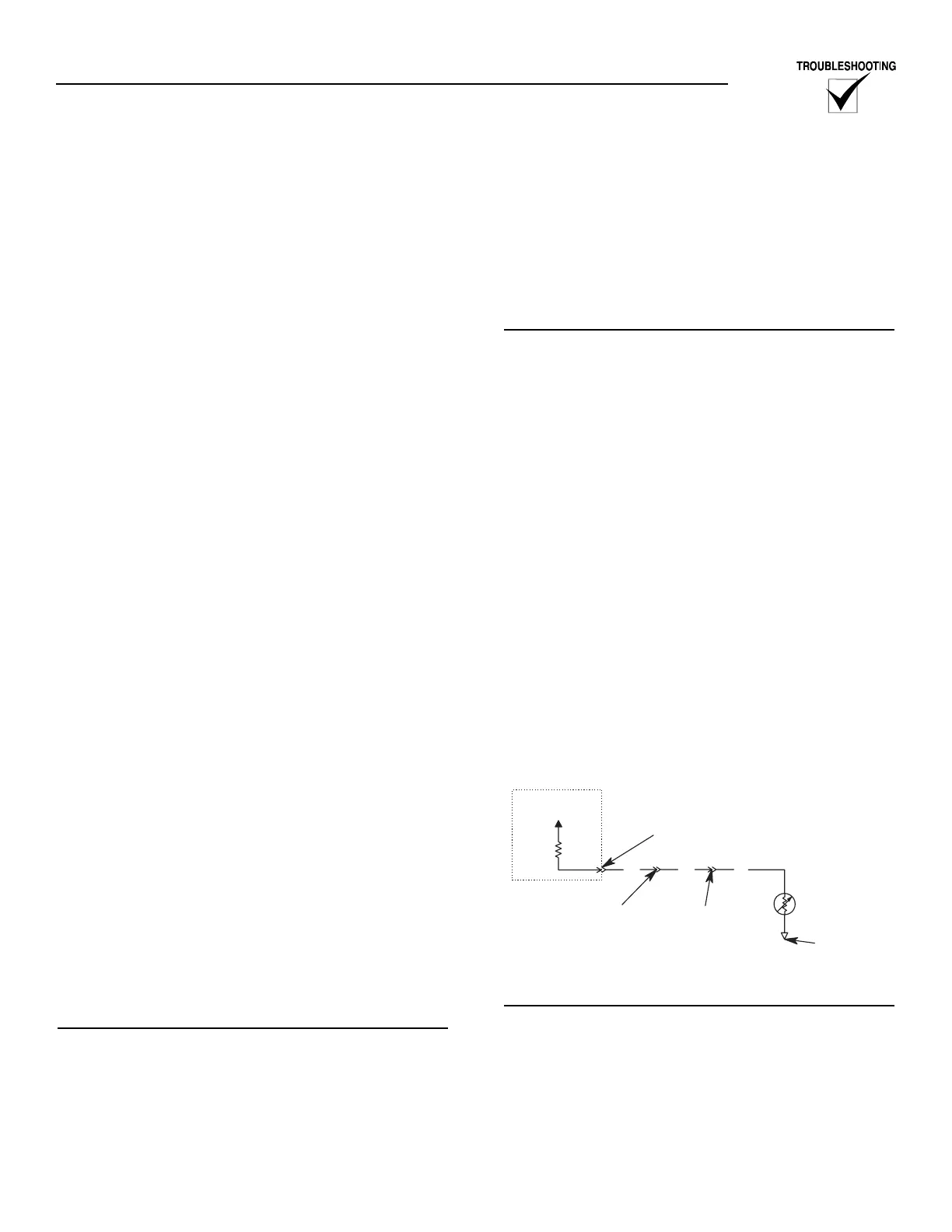
OIL TEMPERATURE SENSING
(Refer to Figure 3.4)
OVERVIEW
Oil Temperature sensing is an OPTION offered with
the E Panel. When ordered, an analog Oil
Temperature Sender (OTS) is mounted in the oil pan.
This sender is connected to the E Panel and allows
the E Panel to monitor and display the temperature
of the engine oil. Wire number 523 is used to connect
the OTS to the E Panel. The ground for the OTS is
made through the oil pan/engine block.
The OTS is a resistive device, whose resistance
changes based on oil temperature. The resistance of
the sender results in a voltage being developed across
the sender. As the oil temperature increases, the
resistance will decrease, causing the voltage to
decrease. This changing voltage is read by the E Panel
and converted to oil temperature.
TROUBLESHOOTING
Prior to any troubleshooting, verify the following:
1. Verify the oil temperature option has been ordered
and installed on the generator.
2. Check and verify the Oil Temperature parameters
programmed into the E Panel. The oil temperature
has two different set points associated with it.
Pre-High Oil Temp Warning: This is a warning
set point. The generator's alarm will sound but the
generator will continue to run. This parameter
should be Disabled if no sender was fitted.
High Oil Temp Alarm: This is an alarm set point.
The generator will shut down and sound the
alarm. This parameter should be Disabled if no
sender was fitted.
It is important to verify that these parameters are set
correctly for the specific unit. Check the E Panel set-
tings against the Generator setup sheet. If the gener-
ator setup sheet is not available, contact Generac's
service department for the recommended settings.
Figure 3.4 — Optional Oil Temperature Sender
Connections
TESTING THE CONTROL PANEL
It is relatively easy to do a thorough test of the E
Panel's Oil Temperature input.
Place the Auto/Off/Manual switch to the Off position
during this testing.