DT Type
Wire Gauge
Range
Strip Length
(inches)
Contact Part
Number
0460-202-20141 20 AWG .156-.218
0462-201-20141 20 AWG .156-.218
0460-202-16141 16, 18 & 20 AWG .250-.312
0462-201-16141 16, 18 & 20 AWG .250-.312
0460-215-16141 14 AWG .250-.312
0462-209-16141 14 AWG .250-.312
0460-204-12141 12 & 14 AWG .222-.284
0462-203-12141 12 & 14 AWG .222-.284
0460-204-08141 8 & 10 AWG .430-.492
0462-203-08141 8 & 10 AWG .430-.492
0460-204-0490 6 AWG .430-.492
0462-203-04141 6 AWG .430-.492
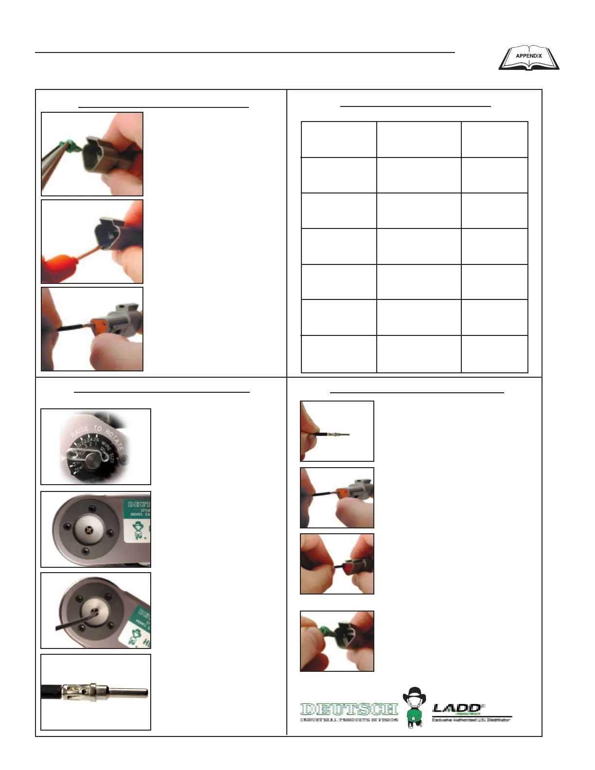
1. Grasp crimped contact
approximately (25.2 mm) one inch
behind the contact barrel.
2. Hold connector with rear
grommet facing you.
3. Push contact straight into
connector grommet until a click
is felt. A slight tug will confirm
that contact is properly locked in
place.
4. Once all contacts are in place,
insert wedgelock with arrow pointing
toward exterior locking mechanism.
The wedgelock will snap into place.
Rectangular wedges are not
oriented. They may go in either way.
NOTE: The receptacle is shown use the
same procedure for plug.
Step 1: Contact Removal
Step 4: Contact Insertion
Step 2: Wire Stripping
1. Remove wedgelock using
needlenose pliers or a hook
shaped wire. Pull wedge
straight out.
2. To remove the contacts,
gently pull wire backwards,
while at the same time
releasing the locking finger
by moving it away from the
contact with a screwdriver.
3. Hold the rear seal in
place, as removing the
contact may displace the
seal.
(800) 223-1236
Solid Contacts
Step 3: Contact Crimping
5. Insert wire into contact.
Contact must be centered
between indicators. Close
handles until crimp cycle is
completed.
6. Release handles and
remove crimped contact.
1. Strip insulation from wire.
(See Step 2).
2. Raise selector knob and
rotate until arrow is aligned with
wire size to be crimped.
3. Loosen locknut, turn adjust-
ing screw in until it stops.
4. Insert contact with barrel up.
Turn adjusting screw counter
clockwise until contact is flush
with indentor cover. Tighten
locknut.
7. Inspect terminal to ensure
that all strands are in crimp
barrel.NOTE: Tool must be
readjusted for each type/size
of contact. Use HDT04-08 for
size 8 and 4 contacts.
Use Crimp Tool #HDT48-00
Appendix — Phoenix and Deutsch Connectors
E Option Control Panels
Generac
®
Power Systems, Inc. 37