Generac
®
Power Systems, Inc. 33
1. Measure the start output directly at CON3-2 on the
back of the E Panel. This should read +12/24V
whenever the E Panel display reads "attempting to
start."
1.1 If it does not, then the E Panel has failed and
needs to be replaced.
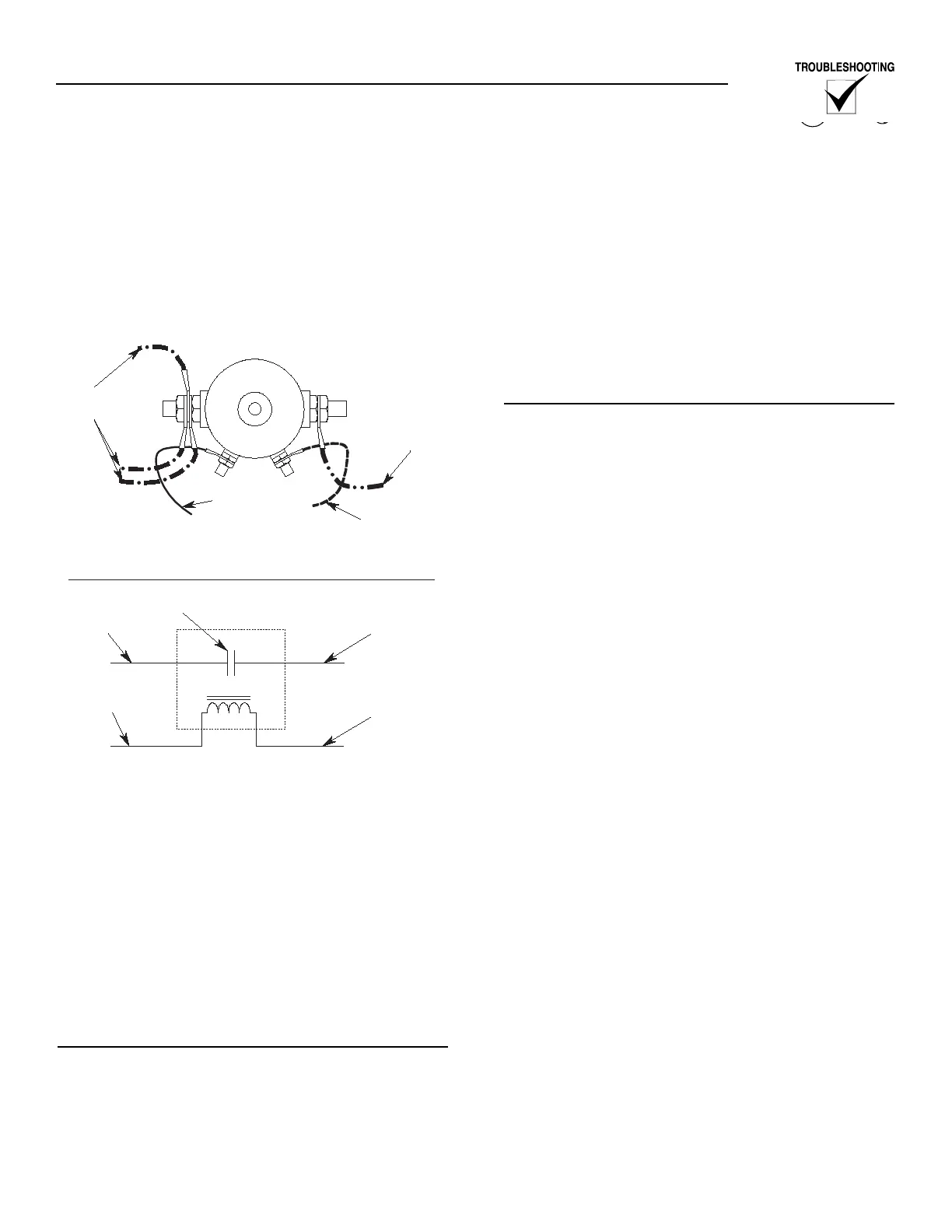
Figure 3.8 — Starter Contactor Connections
1.2 If it does read +12/24V, but the engine does
not crank, then there is nothing wrong with
the E Panel. Proceed to the next test.
2. Measure the 56 location on the control panels
main terminal strip. This should read +12/24V
whenever the E Panel display reads "attempting to
start."
2.1 If it does not, then carefully check the 56 wire
between the E panel and the terminal strip.
2.2 If it does read +12/24V, but the engine does
not crank, move on to the next test.
CHECK THE CONDITION OF THE STARTER
CONTACTOR CONNECTIONS
1. Check for environmental corrosion on the termi-
nals, nuts, or lugs. Generac recommends the fol-
lowing actions if corrosion is found:
1.1 Replace the lugs.
1.2 Thoroughly remove all of the corrosion from
the contactor terminals.
1.3 Protect the lugs and terminals with an
approved automotive dielectric grease.
2. Check to see if the terminal nuts are tightened
securely, but be careful not to over tighten them.
2.1 Coil terminals (10-32 studs and nuts). These
nuts should be tightened to 12 to 15 inch
pounds.
2.2 Contact terminals (5/16-24 studs and nuts).
These nuts should be tightened to 30 to 36
inch pounds.
MEASURE THE START SIGNAL AT THE
STARTER CONTACTOR
1. Measure the 56 connection at the start contactor.
This should read +12/24V whenever the E Panel
display reads "attempting to start."
1.1 If it does not, then carefully check the 56 wire
between the terminal strip and the starter
contactor.
1.2 If it does read +12/24V, but the engine does
not crank, move on to the next test.
2. Check the 0 connection at the starter contactor.
The 0 connection at the starter contactor can be
checked as follows:
2.1 Connect the negative volt meter lead to the 0
at the starter contactor.
2.2 Connect the positive volt meter lead to the a
13/218 location inside the control panel.
2.3 The voltmeter should read +12/24Volts. If it
does not, there is a problem with the 0 con-
nection to the starter contactor. Very carefully
check all 0 connections including the star
ground on the engine block.
3. Measure the 13/218 wire at the starter contactor.
This should read +12/24V any time the battery is
connected.
3.1 If it does not, then carefully check the 13/218
wiring between the battery and the starter
contactor.
3.2 If it does read +12/24V, but the engine does
not crank, move on to the next test.
4. Measure the 16 wire at the starter contactor. This
should read +12/24V whenever the E Panel reads
"attempting to start".
4.1 If it does not, then the starter contactor is bad
and needs to be replaced.
4.2 If it does read +12/24V, but the engine does
not crank, move on to the next test.
5. Measure the 16 wire at the starter motor. This
should read +12/24V whenever the E Panel reads
"attempting to start".
5.1 If it does not, then carefully check the 16 wire
running between the starter contactor and the
starter itself.
3-2 on the E Panel. 56 will be
signal to the engine.