16 Generac
®
Power Systems, Inc.
Section 2 — Operation
E Option Control Panels
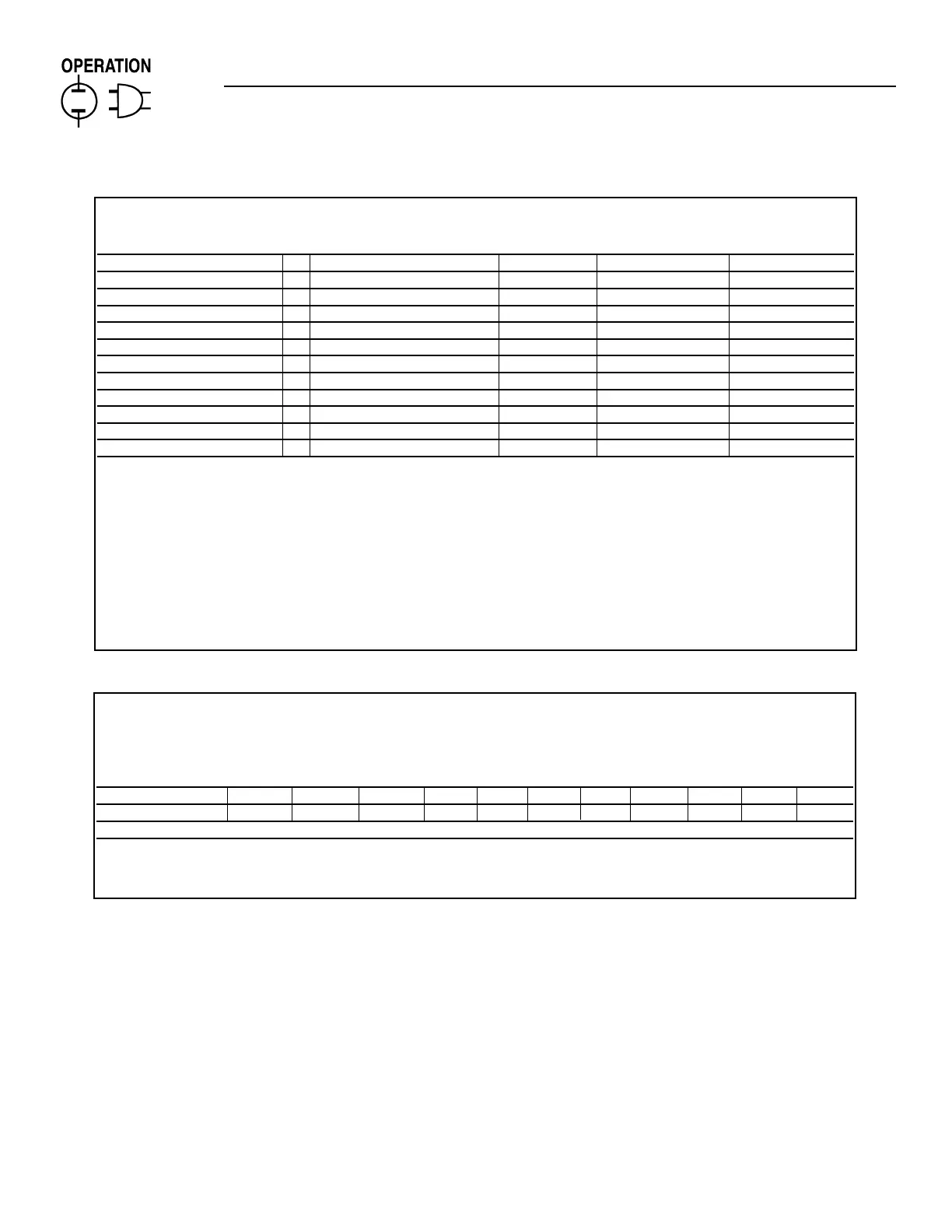
DIGITAL I/O MENU
Channel Message Setting Alarm Enable Alarm Type
Output 1 (F1)
Output 2 (F1)
Output 3 (F1)
Preheat Output Function (F1)
User Input 1 *1 Battery Charge Fail (S1) (A1) (T1)
User Input 2 *1 Generator Power (S1) (A1) (T1)
User Input 3 *1 Line Power (S1) (A1) (T1)
User Input 4 *2 Backup Low Oil Pressure (S1) (A1) (T1)
User Input 5 *2 Backup High Engine Temp. (S1) (A1) (T1)
User Input 6 *2 Oil Filter Blocked (S1) (A1) (T1)
User Input 7 *2 MLCB (S1) (A1) (T1)
User Input 8 *2 Ruptured Tank (S1) (A1) (T1)
Messages can be a maximum of 24 characters including spaces.
Available Options: A1 = Disabled, Hold Off, Immediate, Always
F1 = See output function table for available options.
S1 = Closed (Low Signal/Contact Closure to Ground), Open (High signal/Open Circuit)
T1 = Shutdown Alarm, Latching Alarm, Non-latching alarm, Status Message
*1 Assigned if used with 20 light Remote Annunciator or Remote Relay Panel Otherwise available for any
customer options.
*2 Factory wired if unit is equipped with these options. Otherwise these inputs are available for any
customer requirements.
ANALOG INPUT MENU
Alarm Msg. (Alarm) (Alarm)
Value at Value at (Display) Message Setpoint Enable Type
0V 10V Title High Low High Low High Low High Low
Analog Channel 1 (A1) (A1) (T1) (T1)
Analog Channel 1 (A1) (A1) (T1) (T1)
Messages can be a maximum of 24 characters including spaces.
Available Options: A1 = Disabled, Hold Off, Immediate, Always
T1 = Shutdown Alarm, Latching Alarm, Non-latching alarm, Status Message