30 Generac
®
Power Systems, Inc.
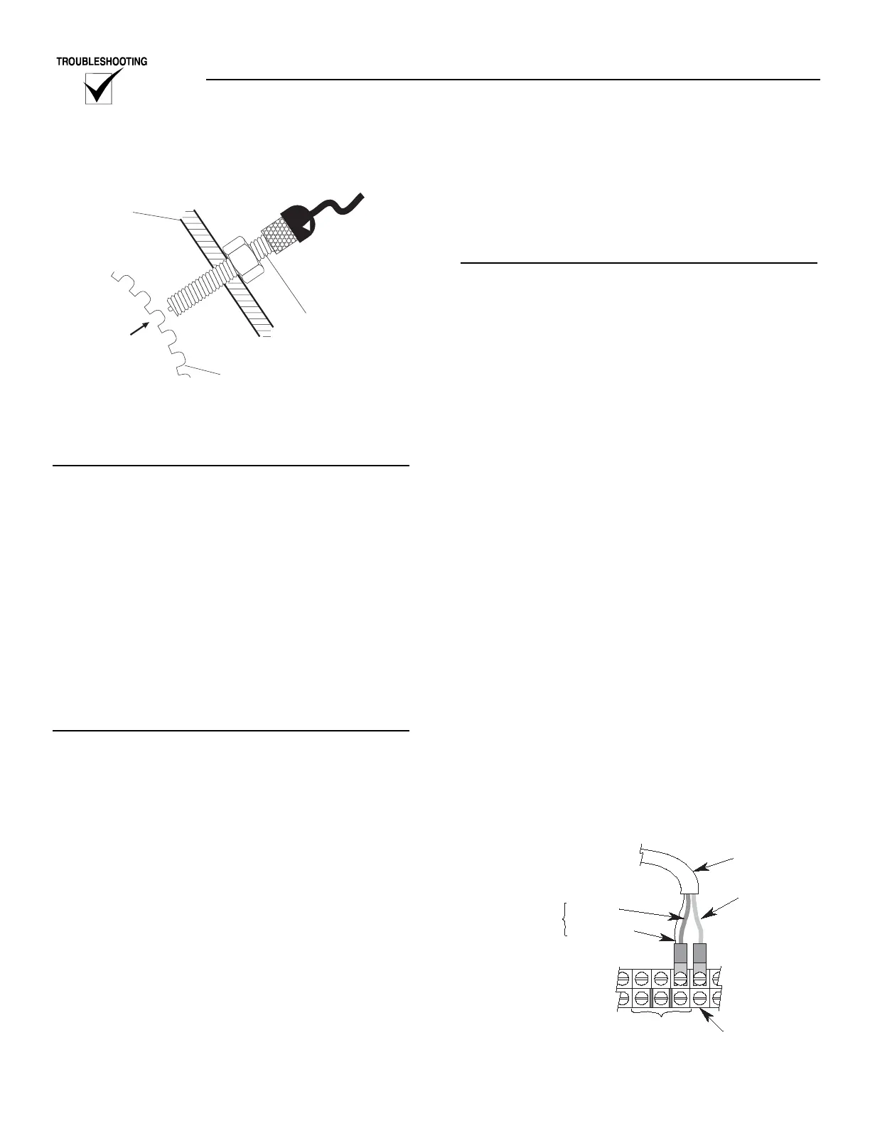
Figure 3.5 — RPM Sensor
If the magnetic pickup is removed for any reason, it
must be installed properly.
INSTALLATION
1. Rotate the ring gear until a gear tooth face is
directly in the center of the tapped hole on the
blower housing.
NOTE:
Do NOT use the alternator fan to rotate the engine.
2. Gently turn the magnetic pick up clockwise into
the tapped hole until it bottoms on the gear tooth.
3. Use a marker to mark a line on the magnetic pick
up threads and blower housing.
4. Using the lines marked in Step 3 as a guide, turn
the magnetic pick up 1/2 to 3/4 of a turn counter-
clockwise.
5. Tighten the jam nut securely.
RELATED ALARMS
RPM Sensor Loss
RPM sensor loss is a shut down alarm. There are two
conditions that will result in RPM sensor loss.
1. No RPM signal at crank. The E Panel will monitor
the RPM sensor during the crank cycle. If no sig-
nal is detected within a few seconds of cranking,
the E Panel will display RPM Sensor Failure and
shut down the engine.
2. RPM sensor loss while running. The E Panel con-
tinues to monitor the RPM sensor while running.
If the signal is lost while running, the E Panel will
display RPM sensor failure and shut down the
engine.
Engine Under Speed
Engine under speed is a hold off alarm with a pro-
grammable set point. The alarm type is programma-
ble as shutdown, latched, non-latched or status.
Engine Over Speed
Engine over speed is an immediate alarm with a pro-
grammable set point. Engine over speed is a shut
down alarm.
TROUBLESHOOTING
1. Verify that all the following parameters have been
correctly programmed into the E Panel.
1.1 Number of flywheel teeth. The number of fly-
wheel teeth is used by the E Panel to convert
the electrical pulses from the RPM sensor,
into engine speed. If this parameter is not
programmed correctly, the E Panel will not be
able to monitor engine speed correctly. Verify
the number of flywheel teeth against the gen-
erator setup sheet. If the generator setup
sheet is not available, contact Generac's serv-
ice department for the REQUIRED setting.
1.2 Over speed and under speed settings. Verify
these settings against the generator setup
sheet. If the generator setup sheet is not avail-
able, contact Generac's service department
for the recommended settings.
2. Check the RPM sensor wiring. A two conductor
shielded cable is used to connect the RPM sensor
to the E Panel. It is important to very carefully
check this wiring and all connections, including
the shield connections.
2.1 Cable description:
2.1.1 Red wire (wire 79). The red wire inside
the cable is wire number 79. This wire
is used to connect the RPM signal from
the sender to the E Panel.
2.1.2 Black wire (wire 0). The black wire
inside the cable is the 0 wire that con-
nects the RPM sensor to the E Panel.
Figure 3.6 — Control Panel RPM Sensor
Connections