12 Generac
®
Power Systems, Inc.
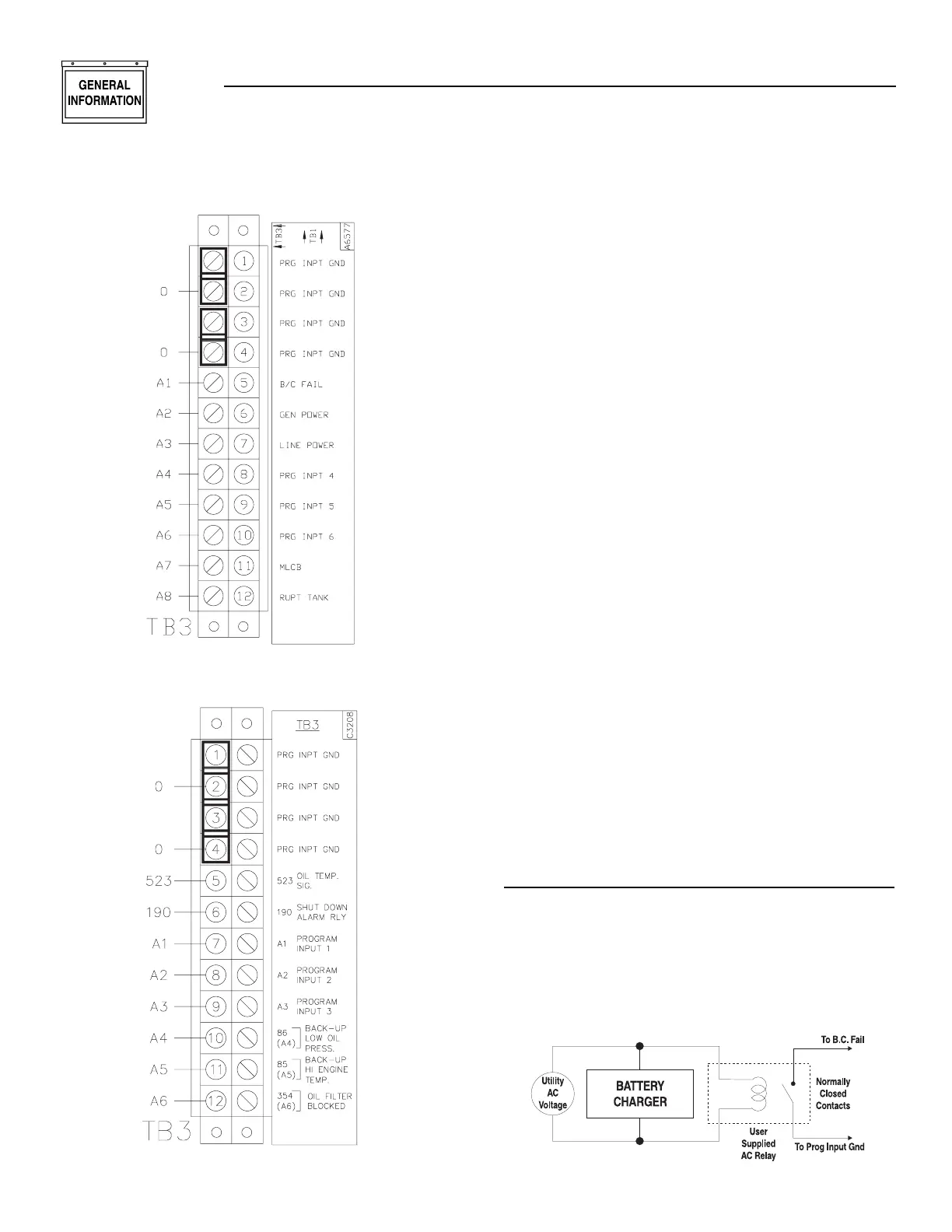
Figure 1.7 — TB3 Units Up to 400 kW
Figure 1.8 — TB3 Units Over 400 kW
The remaining eight terminals on TB3 are for the “pos-
itive” side of each user programmable input switch cir-
cuit. These eight terminals have a five VDC potential
available in an open-circuit condition (whether the
control panel key switch is in the off, manual, or auto
position). The inputs can be programmed to annunci-
ate upon either an open circuit condition (five VDC
potential at the terminal) or a grounded condition
(zero VDC potential at the terminal). This voltage state
is determined by the user supplied switch either open-
ing or closing to cause an annunciation.
Program set-up for the user programmable inputs is
carried out in the Digital I/O Menu of the E module
(please refer to the Display Map on pages 18-19). Each
of the eight inputs has four parameters in which spe-
cific options must be selected to make the annuncia-
tion function properly. These four parameters are
labeled Input Channel Message, Input Channel Setting,
Input Channel Alarm Enable, and Input Channel
Alarm Type. Following is a brief description of each:
• Input Channel Message — for selecting letters and
numbers to spell out what the display will read
upon activation of that specific input.
• Input Channel Setting — for selecting whether
annunciation should activate upon that specific
circuit opening or closing to ground.
• Input Channel Alarm Enable — for enabling or dis-
abling annunciation function of that specific input.
Also, if enabled, for selecting when annunciation
will be active. The choices are: Disabled, Always,
Immediate and Hold-off. See E Control Panel
Definitions on page 38.
• Input Channel Alarm Type — for selecting the type
of alarm annunciation and the effect it has on the
generators control system. The four choices are:
Status, Non-latched, Latched and Shutdown. See
E Control Panel Definitions on page 14.
WIRING EXAMPLES
USER PROGRAMMABLE INPUT NUMBER 1
On units rated below 400 kW, input number 1 is pro-
grammed for “Battery Charge Fail” annunciation at
the control panel display, and the LED on the 20 Light
Remote Annunciator (if used). A user supplied AC
relay is wired in to be powered up by AC voltage that
supplies the unit Battery Charger (see Figure 1.9).
Figure 1.9 — Battery Charge Fail Wiring
◆
Section 1 — General Information
E Option Control Panels