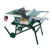
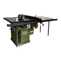
1. Loosen the bevel lock knob F by turning it counter-
clockwise.
2. Using the graduated scale G as a guide, turn the
handwheel left or right as required to set the blade to
the desired angle. The blade can be tilted to the left
anywhere from 0° (90° to the table) to 45°.
3. With the blade tilted to the desired angle, tighten the
lock knob by turning it clockwise to lock the tilting
mechanism and secure the blade.
Note: Never use a dado blade in a bevel position.
BLADE TILT (BEVEL) ADJUSTMENT
31
The riving knife mounting block is already factory set,
and should not require adjustment out of the box. How-
ever with use over time, re-alignment may be required
periodically.
The splitter/knife mounting bracket consists of an arm
A, a spacer B, and a hold-down block C. This assembly
is held together by two locking screws D. Both 90º to the
table and parallel/centered to the blade alignments
can be achieved by adjusting the four set screws E.
To be able to adjust the set screws, the locking screws
D must first be loosened (with a 4 mm Allen key) – 1/4
turn or more, depending upon how much adjustment
is required.
RIVING KNIFE ADJUSTMENT
1/4”
TO LIMIT YOUR EXPOSURE TO THE BLADE NEVER TAKE MORE BLADE HEIGHT THAN IS REQUIRED TO COMPLETE
THE CUT. WHEN SETTING THE BLADE HEIGHT FOR THROUGH-CUTS (CUTS ALL THE WAY THROUGH THE THICK-
NESS OF A BOARD) SET THE HEIGHT OF THE BLADE TO ROUGHLY 1/4” HIGHER THAN THE THICKNESS OF THE
BOARD.
MAIN BLADE AND SCORING BLADE HEIGHT ADJUSTMENT
The blade height adjustment handwheels are located
on the front of the machine and there are two lock
knobs A and B that allow you to lock the handwheels
and secure the blades at the desired height.
To raise or lower the main blade:
1. Loosen the blade height lock knob A by turning it
counterclockwise.
2. To raise the blade: turn the handwheel C clockwise.
To lower the blade: turn the handwheel C counter-
clockwise.
3. With the blade set to the desired height, tighten the
lock knob A by turning clockwise to lock the blade
in place.
To raise or lower the scoring blade:
1. Loosen the blade height lock knob B by turning it
counterclockwise.
2. To raise the scoring blade: turn the handwheel D
clockwise.
To lower the scoring blade: turn the handwheel D
counterclockwise.
Note: The scoring blade should be raised a few millimeters
above the table surface just enough to score the panel's sur-
face.
3. With the scoring blade set to the desired height,
tighten the lock knob B to lock the blade in place.
A
B
C
B
D
F
E
G
 Loading...