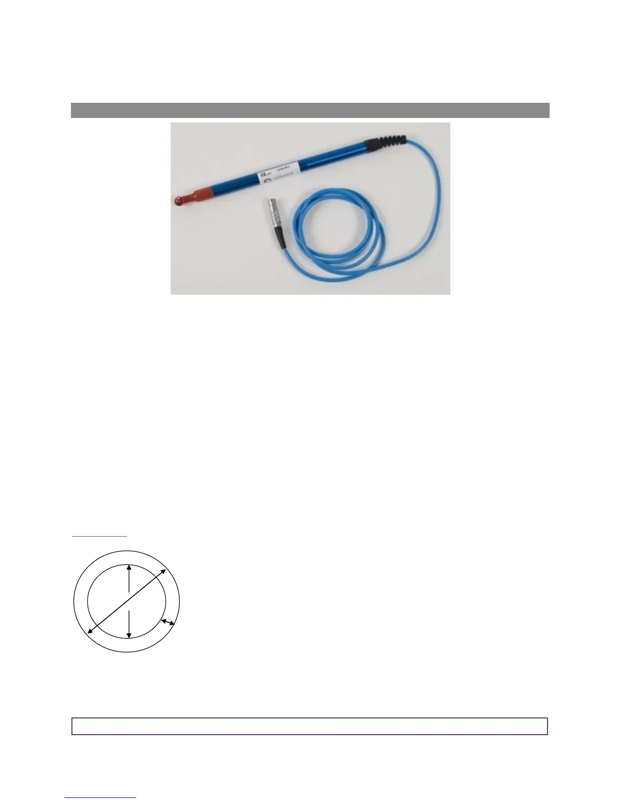
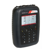
How to use an anemometer (optional)
The GEM5000 gas analyser has the facility to attach an anemometer device enabling the site engineer to
measure the flow of gas within an extraction system. The anemometer can be set to display two values; m/s
(meters per second) and m3/hr (metres cubed per hour).
It is best practice to take the gas reading first before taking the flow reading with the anemometer attached.
If using a ‘borehole ID’ the internal pipe diameter can be predetermined in the optional Gas Analyser Manager
(GAM) software. Once set, the site engineer cannot edit the pipe diameter setting.
If the site engineer is not using a borehole ID or the pipe diameter is not set in GAM the operator will be
prompted to enter a pipe diameter with a new ID on the analyser. Select soft-key ‘Next ID’ from the Main Gas
Read screen, followed by soft-key ‘Add’ and add a new borehole location.
In order to use the anemometer it is important to know the internal diameter (ID) of the pipe if you want to
calculate the flow in m3/hr (metres cubed per hour). This must be the internal diameter not the outer diameter
(OD) i.e. pipe outer diameter minus twice the pipe wall thickness.
For example:
If you do not have any suitable monitoring points you will need to drill (tap of ¾” BSP pipe thread) a hole in the
piping of between 25mm and 30mm in diameter to seat the conical fitting on the anemometer (which is roughly
between 20mm to 34mm). When not in use the hole can be re-sealed with a ¾” BSP male bung.