ECturn/ECturn Inside
28
Mains connection
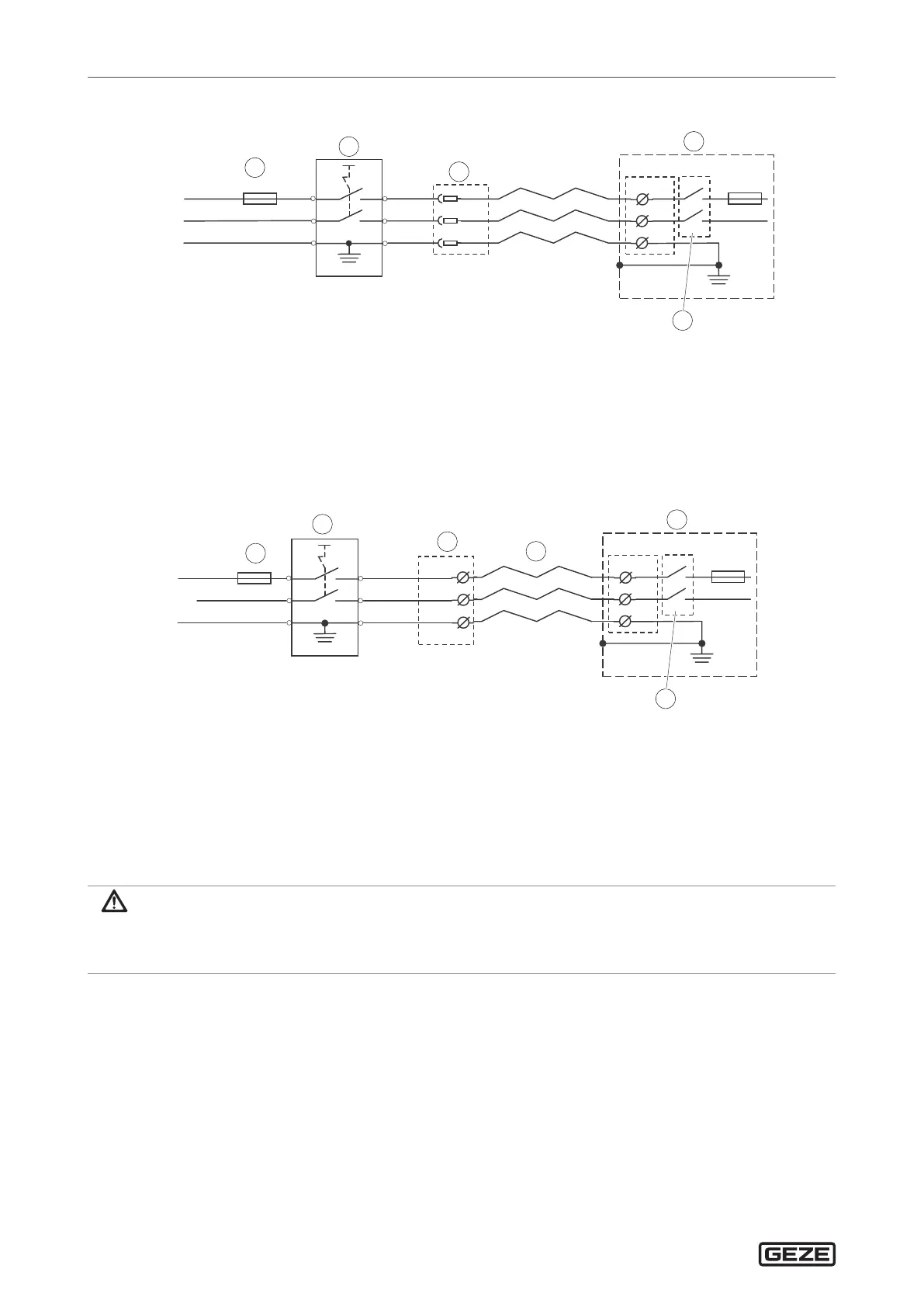
15.1.1 Mains connection for transom installation
BK
BU
GN/YE
L
N
PE
PE
1
BK
BU
GN/YE
L
N
DCU702
L
N
F1
T4A
4
5
3
2
1
1 Mains fuse provided on site
2 Main switch provided on site (optional)
3 Earth-pin power socket (provided on site)
4 ECturn drive unit
5 Mains switch
15.1.2 Mains connection for door leaf installation
Door transmission cable ECturn, mat. no. 135307
BK
BU
GN/YE
L
N
PE
PE
1
BK
BU
GN/YE
L
N
1
2
3
4
F1
T4A
6
1 Mains fuse provided on site
2 Main switch provided on site (optional)
3 Connection box (provided on site)
4 ECturn door transmission cable
5 ECturn drive unit
6 Mains switch
15.2 Mains connection for ECturn Inside
DANGER
Danger of electric shock!
X
Have connection of the power supply to the mains voltage carried out by a qualied electrician.
X
Perform the power connection and equipment earth conductor test in accordance with VDE 0100 Part 600.
à Power supply NT 3.83A-24V HS, mat. no. 196761
à Surface-mounted power supply housing, mat. no. 152010
à Max. cable length power supply – door controller: 20 m
à Wire cross-section for the connection power supply – door controller: 1 mm
2
.
X
Mount the power supply in a distributor cabinet or in a surface-mounted power supply housing.
X
Slide the ferrite sleeve over the cable power supply – door controller and position it direct at the DCU703
control unit.