WindMaster and WindMaster Pro 1561-PS-0001. Issue 11 February 2017
________________________________________________________________________________________________________________________
14
The table shows some suitable manufacturers’ references; other manufacturers’ equivalents can be used.
The cable allows for the connection of all: -
Power inputs.
Digital data inputs and outputs.
Analogue inputs.
Analogue Outputs.
Note: If PRT input option is selected customer must compromise on the number of enclosed inputs or outputs. If a PRT
is connected you must sacrifice two analogue inputs or outputs.
Other example twisted pair screened cable types (24AWG) are:-
6.4. Cable length
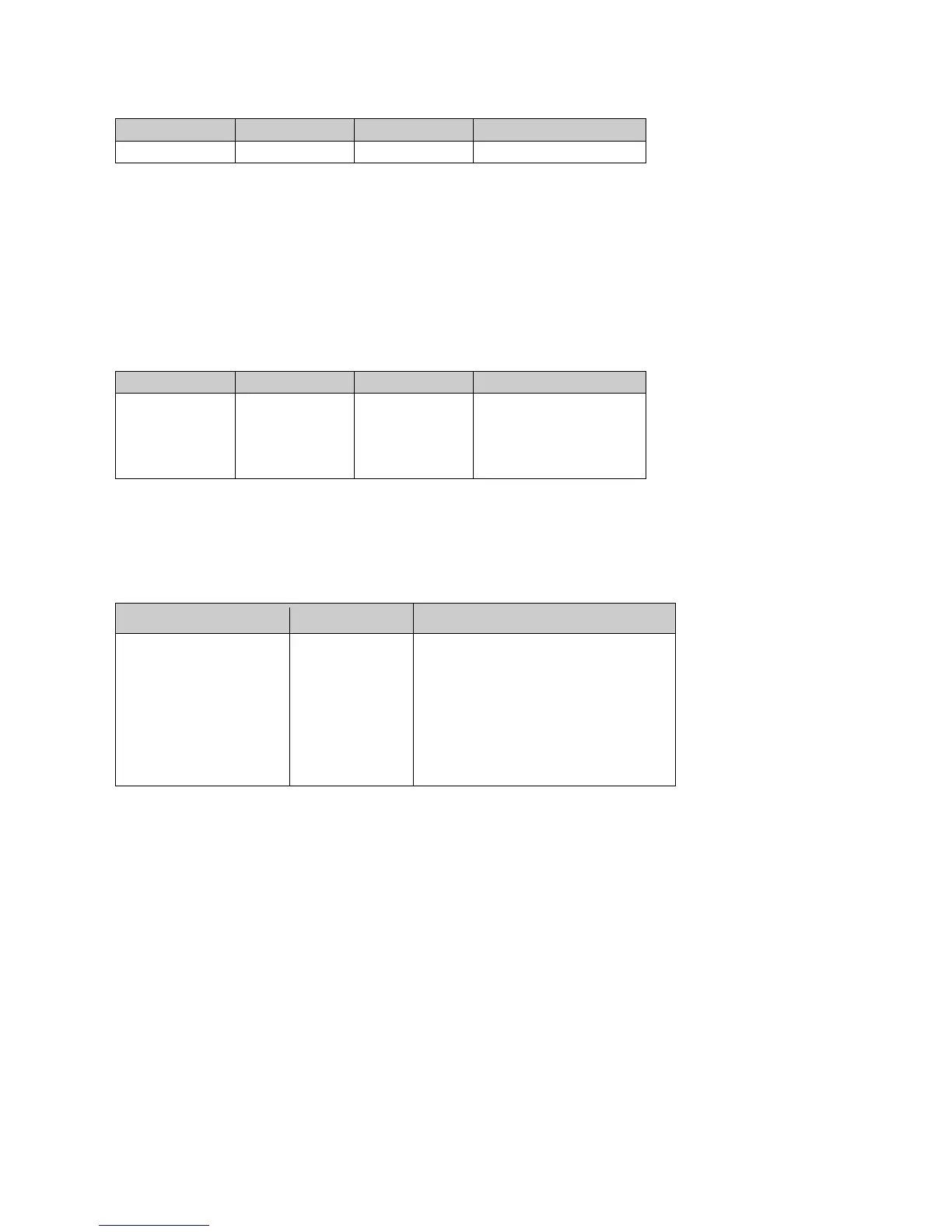
The maximum cable length is dependent on the chosen communication format (RS232, RS422 or RS485), the baud
rate, and, to a lesser extent, on the cable type and the local electrical ‘noise’ level.
6.5 m (20 ft) or if using Cat 5 cable see
manufacturers recommendations
Resistance dependent (max 300 Ω)
The above table shows the typical maximum lengths at the given baud rates, using the recommended cable. If any
problems of data corruption etc. are experienced, then a slower baud rate should be used. Alternatively, a thicker or
higher specification cable can be tried.
6.5. Grounding (Earthing)
To ensure correct operation, and for maximum protection against lightning, the anemometer MUST be correctly
grounded (earthed) via its mountings. Inadequate grounding will degrade anemometer performance, particularly in the
presence of radio frequency interference.
The unit MUST be connected to an appropriate grounding point with a minimum of 6mm² copper wire, via the M6 base
screws. The primary earth for the anemometer must be provided via the base screws and not via the cable screens.
 Loading...